
A polarization maintaining fiber

A polarization-maintaining fiber and fiber core technology, which is applied in polarization fiber, cladding fiber, multi-layer core/cladding fiber, etc., can solve the problem that the environmental performance has a large impact, cannot meet the needs of fiber optic gyroscope development, and is difficult to take into account at the same time. FOG development requirements and other issues, to achieve the effect of reducing side lobes, avoiding reliability reduction, and high-performance crosstalk output

Active Publication Date: 2020-05-05
FENGHUO COMM SCI & TECH CO LTD +1
View PDF7 Cites 0 Cited by
  • Summary
  • Abstract
  • Description
  • Claims
  • Application Information

AI Technical Summary

Problems solved by technology

[0006] At present, there are thin-diameter polarization-maintaining optical fibers in the market, such as a kind of thin-diameter polarization-maintaining optical fiber provided by the patent publication number CN104536085B, which still has the problem of being greatly affected by environmental performance, and it is difficult to simultaneously miniaturize and high-precision fiber optic gyroscope The research and development needs of the fiber optic gyroscope cannot meet the growing needs of the fiber optic gyroscope

Method used


Image

  • A polarization maintaining fiber
  • A polarization maintaining fiber
  • A polarization maintaining fiber

Examples


Embodiment 1

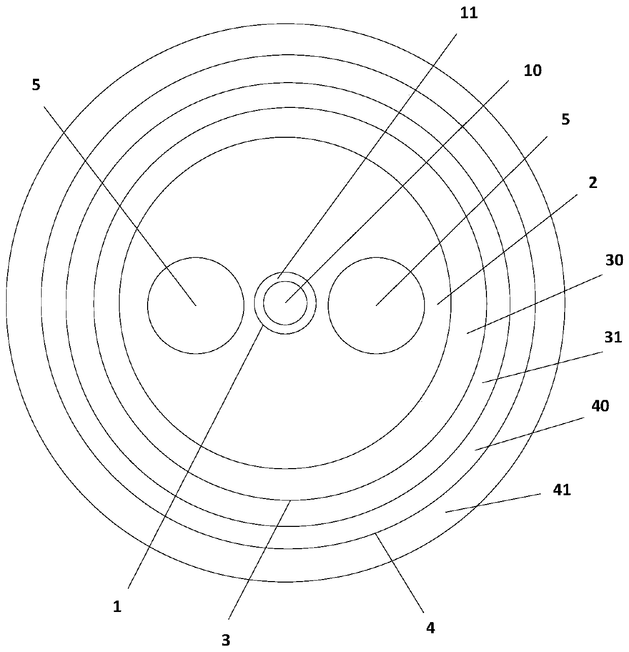
[0028] See figure 1 As shown, the embodiment of the present invention provides a polarization-maintaining fiber, which includes a core 1, a quartz cladding 2, an inner coating 3, and an outer coating 4 from the inside to the outside. The quartz cladding 2 is located in the core At the periphery of 1, two stress regions 5 are provided between the quartz cladding 2 and the core 1, and the two stress regions 5 are symmetrically distributed along the center of the core 1;

[0029] The core 1 includes a circular central core region 10 and at least one annular region 11 arranged concentrically with the central core region 10 from the inside to the outside, and the central core region 10 and the annular region 11 have different refractive indexes;

[0030] The inner coating 3 and the outer coating 4 both have a double-layer structure, and the modulus of each layer of the inner coating 3 and the outer coating 4 is different, and the modulus increases from the inner to the outer layer.

[003...

Embodiment 2

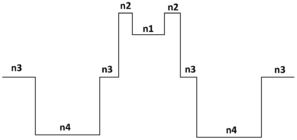
[0033] See figure 2 As shown, the difference between this embodiment and Embodiment 1 is that the refractive index of the central core region 10 is n1, the refractive index of the annular region 11 is n2, and the refractive index of the quartz cladding 2 is n3, so The refractive index of the stress region 5 is n4, and n4

[0034] The refractive index of the central core region 10 relative to the quartz cladding 2 is △n1, and the refractive index of the annular region 11 relative to the quartz cladding 2 is △n2, △n1<△n2, where the value of △n1 The range is 0.4% to 1.3%, and the value range of △n2 is 0.6% to 1.5%.

[0035] In the embodiment of the present invention, the refractive index n1 of the central core region 10 is smaller than the refractive index n2 of the annular region 11, that is, the core forms a U-shaped structure design, so that the mode characteristics of the optical signal transmitted by the polarization maintaining fiber tends to be more intermediate. R...

Embodiment 3

[0037] The difference between this embodiment and embodiment 1 is that the diameter of the central core region 10 is d1, the outer diameter of the annular region 11 is d2, the diameter of the stress region 5 is d3, and the diameter of the quartz cladding 2 The outer diameter is d4, and d1


PUM

PropertyMeasurementUnit
modulusaaaaaaaaaa
modulusaaaaaaaaaa
modulusaaaaaaaaaa

Abstract

The invention discloses a polarization-maintaining optical fiber, which relates to the field of optical fibers. The polarization-maintaining optical fiber comprises a core, a quartz cladding, an inner coating and an outer coating in sequence from the inside to the outside, and the quartz cladding is located on the periphery of the fiber core. , there are two stress regions between the silica cladding and the fiber core, and the two stress regions are symmetrically distributed along the center of the fiber core; the fiber core sequentially includes a circular central core from the inside to the outside region and at least one annular region concentrically arranged with the central core region, the refractive indices of the central core region and the annular region are different; The moduli of the layer and the outer coating are different, and the modulus increases sequentially from the inside to the outside. The polarization-maintaining optical fiber provided by the invention provides more stable and higher-performance crosstalk output and optical fiber attenuation performance.

Description

Technical field [0001] The invention relates to the field of optical fibers, in particular to a polarization maintaining optical fiber. Background technique [0002] Compared with other types of gyroscopes, fiber optic gyroscopes have many advantages such as short start-up time, simple structure, light weight, no moving components, and strong environmental adaptability. In recent years, fiber optic gyroscopes have developed rapidly. They are used in navigation systems and navigation systems for aircraft, automobiles, and ships. Motion detection has been widely used in many fields, and with the development of its accuracy improvement and structural miniaturization, it has gradually become a key inertial component for various high-tech navigation and positioning. [0003] The common fiber optic gyroscope is composed of two parts: optical meter and circuit. The optical meter consists of a light source, an optical waveguide, a coupler, an optical fiber sensor, and a detector. The opt...

Claims


Application Information

Patent Timeline
Patent Type & Authority Patents(China)
IPC IPC(8): G02B6/024G02B6/036
CPCG02B6/024G02B6/03638G02B6/0365G02B6/03611G02B6/03633C03B2201/10C03B2201/31C03B2203/31G02B6/03694G02B6/02028C03C25/1065
Inventor 罗文勇赵梓森戚卫柯一礼杜城张涛王毕
Owner FENGHUO COMM SCI & TECH CO LTD
Learn More