Fiber-laser with intracavity polarization maintaining coupler providing plane polarized output

a fiber-laser and coupler technology, applied in the direction of laser details, basic electric elements, electrical equipment, etc., can solve the problems of depolarized output radiation, change of mode polarization, and difficulty in controlling this polarization

Inactive Publication Date: 2006-08-03
COHERENT INC
View PDF14 Cites 32 Cited by
  • Summary
  • Abstract
  • Description
  • Claims
  • Application Information

AI Technical Summary

Problems solved by technology

Superposition of these modes results in the depolarized output radiation.
Further, the random birefringence in the nominally isotropic fibers may result in changes of mode polarization with time due to temperature variations.
Polarization controllers can help to convert this radiation into a linear polarization, but temperature variations and a broad radiation frequency spectrum make it hard to control this polarization.
Changes in the birefringence properties of the optical fiber over time necessitate readjustment of the polarization controller, a problem which makes such a fiber-laser unsuitable for many practical applications.
This type of a polarizer, however, exhibits high insertion loss, for example greater than 0.5 decibels (dB), for the preferred polarization.
Further, use of this bulk polarizer is usually limited to low power applications, for example, applications where average power less than about 500 milliwatts (mW) is required.
This is because of a low threshold for optical (laser radiation) damage in the micro-optics assembly.
This type of polarizer, however, exhibits even higher insertion loss, for example, greater than about 1.5 dB in a laser cavity than the above-discussed bulk polarizer.
The source of this insertion loss results from losses at spliced junctions of the non-round core of the fiber-polarizer with the round core of other fiber components of the laser.
This results in stress-induced birefringence in the gain-fiber.
A disadvantage of this method is that it is optimally effective only for large mode-area, low-NA optical fibers.
A further disadvantage is that spooling of such fiber is not a repeatable process, and strongly depends on fiber quality.

Method used


Image

  • Fiber-laser with intracavity polarization maintaining coupler providing plane polarized output
  • Fiber-laser with intracavity polarization maintaining coupler providing plane polarized output
  • Fiber-laser with intracavity polarization maintaining coupler providing plane polarized output

Examples


Embodiment Construction

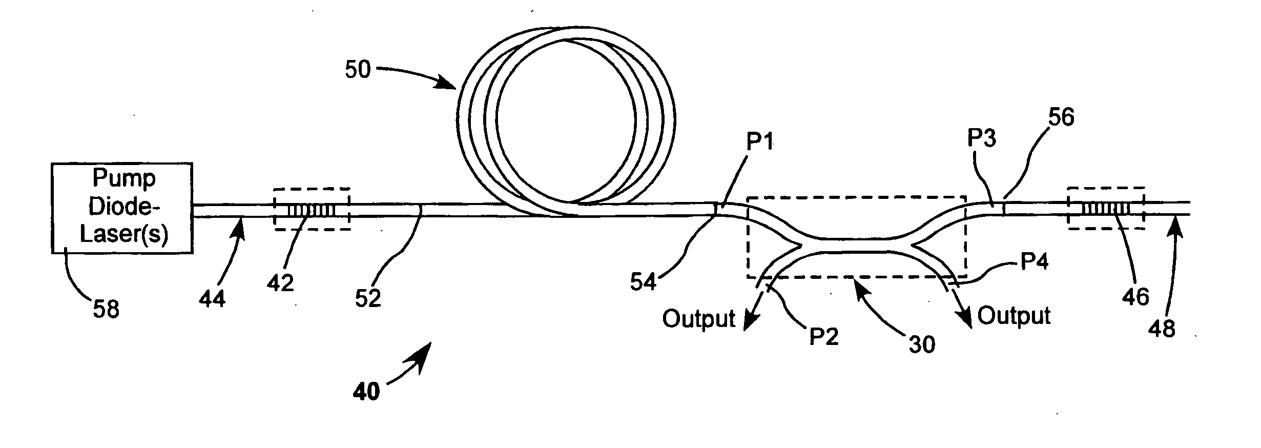
[0046] As summarized above, a fiber-laser in accordance with the present invention provides polarized output by including a polarization maintaining coupler (PM-coupler) in a fiber-laser cavity. Preferably, the gain fiber of the cavity and other optical fibers in the cavity are PM-fibers.

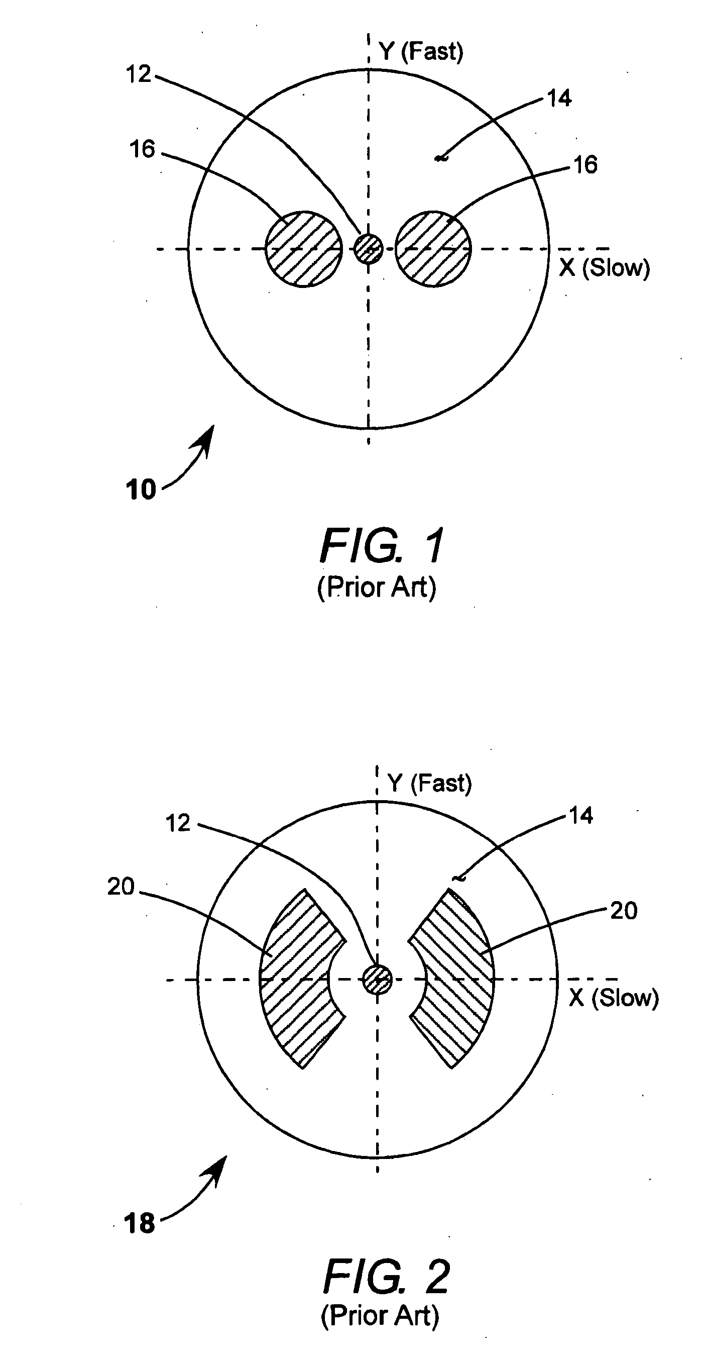
[0047] Referring now to the drawings, wherein like components are designated by like reference numerals, FIG. 5 and FIG. 5A schematically illustrate one example 30A of a PM-coupler in which light is coupled between two above-described Panda PM-fibers 10 designated as PM-fibers 10A and 10B in FIG. 5 to facilitate description. The fibers are partially tapered with claddings thereof fused together over a length L, and with cores 12 thereof (indicated in phantom in FIG. 5) spaced apart by a distance S. PM-coupler 30A can be defined as having four ports, indicated as ports 1-4 in FIG. 5. Ports 1 and 3 are at opposite ends of PM-fiber 10A. Ports 2 and 4 at opposite ends of PM-fiber 10B. The coupler is ar...


PUM


Abstract

A fiber-laser comprises a laser cavity including a gain-fiber. A polarization maintaining fiber coupler (PM-coupler) located in the laser cavity and configured such that the fiber-laser delivers plane-polarized output radiation. The laser cavity may be configured as a linear cavity or as a ring cavity and operated in either cavity configuration in CW or pulsed modes. The PM-coupler, while providing the function of a intra-cavity polarizing element, can additionally function as a wavelength division multiplexing (WDM) coupler. Preferred embodiments of the laser include an intracavity polarization maintaining WDM element functioning jointly as an intra-cavity polarizing element and an element for coupling pump light into the cavity.

Description

TECHNICAL FIELD OF THE INVENTION [0001] The present invention relates in general to optical fiber lasers (hereinafter simply fiber-lasers). The invention relates in particular to fiber-lasers having polarized output. DISCUSSION OF BACKGROUND ART [0002] A fiber-laser can be regarded as an efficient converter of low-brightness multimode radiation from a diode-laser or a plurality of such lasers to high-brightness single-mode radiation. The low-brightness radiation is used to optically pump the fiber laser, which delivers the high-brightness single-mode radiation as a result of the optical pumping. Fiber-lasers are increasingly used in applications that require compact and robust monolithic laser design, good stability and excellent beam quality. The excellent beam quality results, inter alia, from the single-mode characteristic and a uniform symmetrical beam cross section of radiation that can be delivered. In many of the applications, the laser radiation is required to be plane polar...

Claims


Application Information

Patent Timeline
Patent Type & Authority Applications(United States)
IPC IPC(8): H01S3/30
CPCH01S3/06712H01S3/0675
Inventor STARODOUMOV, ANDREIBETTENCOURT, SKIPCRITTENDEN, PAUL
Owner COHERENT INC
Why Eureka
Try Eureka