
Auxiliary laying structure for cable line

A cable and bridge technology, which is applied in the field of cable laying, can solve the problems of damaged cable sheath, difficult maintenance, troublesome pulling and laying cables, etc.

Inactive Publication Date: 2018-11-20
张多艳
View PDF0 Cites 0 Cited by
  • Summary
  • Abstract
  • Description
  • Claims
  • Application Information

AI Technical Summary

Problems solved by technology

[0002] When laying a variety of cable directions in the bridge groove, the operator is often on the cable bridge to pull and lay the cables in the bridge groove. It is troublesome to pull and lay cables, and it is easy to cause damage to the sheath of the pulled cables, which makes maintenance difficult. Therefore, we design an auxiliary laying structure for cables

Method used


Image

  • Auxiliary laying structure for cable line

Examples


Embodiment Construction

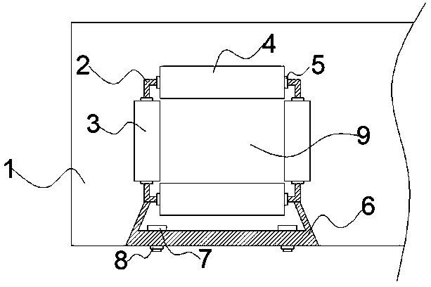
[0013] Such as figure 1 As shown, the present invention discloses an auxiliary laying structure for cables, including: a bridge slot 1, an auxiliary laying structure, the bridge slot 1 is provided with an auxiliary laying structure, and the auxiliary laying structure includes a square pole frame A vertical rotating block 3 is installed on the both sides of the 2, and a horizontal rotating block 4 is installed on the top rod and the bottom rod of the square rod frame 2 respectively. The bottom rod of the square rod frame 2 and the bottom rod The base frame 6 is fixedly welded and connected, and the base frame 6 is locked and installed on the bottom plate of the bridge groove 1 through the fixing bolt 7 , and the locking nut 8 is installed on the fixing bolt 7 .

[0014] A cable avoidance hole 9 is enclosed between the horizontally rotating block 4 and the vertically rotating block 3 , and the cable avoiding hole 9 is used for passing through the laid cables.

[0015] Both side...


PUM


Abstract

The invention discloses an auxiliary laying structure for a cable line. The auxiliary laying structure is arranged in a bridge groove. In the auxiliary laying structure a vertical rotation block is rotatably arranged on each of two side rods of a square rod rack, a horizontal rotation block is rotatably arranged on each of a top rod and a bottom rod of the square rod rack, the bottom rod of the square rod rack is fixedly welded and connected with a base rack, the bottom rack is locked and arranged on a bottom plate of the bridge groove by a fixed bolt, and a locking nut is tightly screwed andarranged at the fixed bolt. With the adoption of the technical scheme, the auxiliary laying structure is simple and is convenient to assemble and install and reliable to fix and use, the cable in thebridge groove is convenient to pull and lay in a guidance way, time and labor are saved by guided traction and laying, and the auxiliary laying structure is relatively good in applicability.

Description

technical field [0001] The invention relates to an auxiliary laying structure for cables, which is applied to the technical field of cable laying. Background technique [0002] When laying a variety of cable directions in the bridge groove, the operator is often on the cable bridge to pull and lay the cables in the bridge groove. Traction and laying of cables is more troublesome, and it is easy to cause damage to the sheath of the traction cables, which makes maintenance difficult. Therefore, we design an auxiliary laying structure for cables. Contents of the invention [0003] In order to solve the defects of the prior art solutions, the invention discloses an auxiliary laying structure for cables. [0004] The invention discloses an auxiliary laying structure for cables, comprising: a bridge slot and an auxiliary laying structure, the auxiliary laying structure is provided in the bridge slot, and the two side poles of the square pole frame included in the auxiliary layi...

Claims


Application Information

Patent Timeline
Patent Type & Authority Applications(China)
IPC IPC(8): H02G3/04
CPCH02G3/0406
Inventor 张多艳
Owner 张多艳
Learn More