
Automatic cleaning device for computer display screen

An automatic cleaning and display screen technology, applied in the direction of using tools, cleaning methods and utensils, removing smoke and dust, etc., can solve the problems of affecting the mood of use, unsightly display screen, waste of labor, etc., to reduce manpower cleaning, Compact structure and labor saving effect

Inactive Publication Date: 2018-11-23
柳州大蘑王网络科技有限公司
View PDF0 Cites 3 Cited by
  • Summary
  • Abstract
  • Description
  • Claims
  • Application Information

AI Technical Summary

Problems solved by technology

[0002] Computer display screen is usually also called computer monitor or computer screen. It is the most important computer component besides CPU and motherboard. It displays certain electronic file information on the screen through a specific transmission device and then reflects it to the screen. A display tool for the human eye, a dirty display screen is not only unsightly, but also affects people's mood in use. Therefore, there is an increasing demand for automatic cleaning devices for computer display screens
[0003] Most of the automatic cleaning devices for computer screens on the market are mostly cleaned manually, which is not only troublesome, but also wastes labor. The traditional automatic cleaning devices for computer screens need to be disassembled and cleaned after cleaning once. , and then install it for subsequent cleaning and use, which is not only a waste of time, but also inconvenient to use. Therefore, in view of the above problems, an automatic cleaning device for computer display screens is proposed

Method used


Image

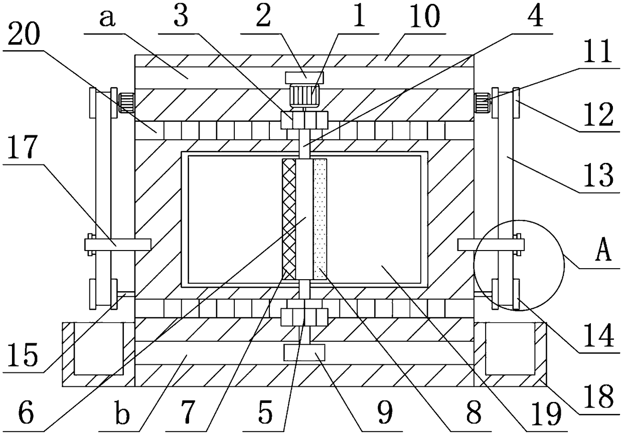
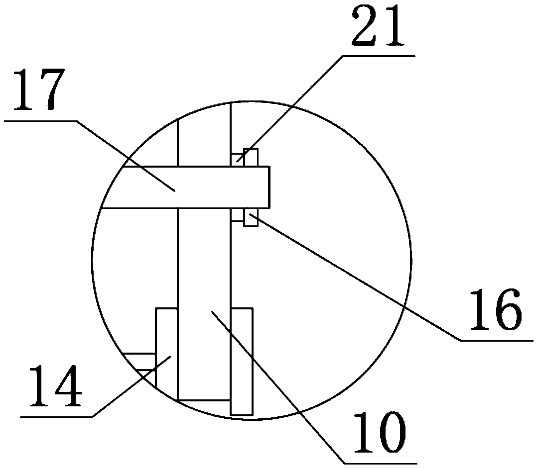
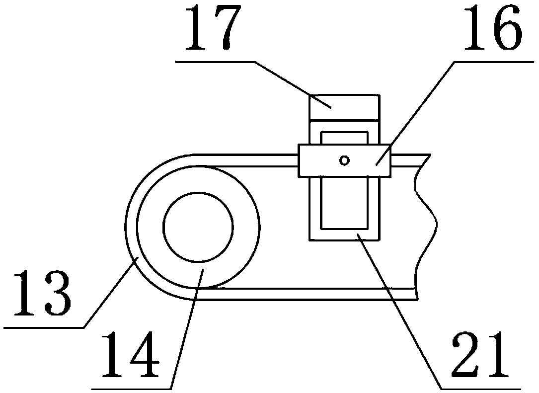
  • Automatic cleaning device for computer display screen
  • Automatic cleaning device for computer display screen
  • Automatic cleaning device for computer display screen

Examples


Embodiment Construction

[0018] The following will clearly and completely describe the technical solutions in the embodiments of the present invention with reference to the accompanying drawings in the embodiments of the present invention. Obviously, the described embodiments are only some, not all, embodiments of the present invention. Based on the embodiments of the present invention, all other embodiments obtained by persons of ordinary skill in the art without making creative efforts belong to the protection scope of the present invention.

[0019] see Figure 1-3 , the present invention provides a technical solution:

[0020] An automatic cleaning device for a computer display screen, comprising a first motor 1 and a first slider 2, the top of the first motor 1 is fixedly connected with the first slider 2, and the end of the main shaft of the first motor 1 is fixedly connected There is a driving gear 3, the bottom end of the driving gear 3 is fixedly connected with a rotating shaft 4, the outer ...


PUM


Abstract

The invention relates to the technical field of cleaning equipment, in particular to an automatic cleaning device for a computer display screen. The automatic cleaning device for the computer displayscreen comprises a first motor and a first sliding block. The first sliding block is fixedly connected with the top end of the first motor. A driving gear is fixedly connected with the tail end of a spindle of the first motor. A rotary shaft is fixedly connected with the bottom end of the driving gear. A driven gear is fixedly connected with the outer side of the rotary shaft. A movable ring is rotationally connected with the outer side of the rotary shaft. A sweeping plate is fixedly connected with the left end of the movable ring. A scraper blade is fixedly connected with the right end of the movable ring. A second sliding block is rotationally connected with the bottom end of the rotary shaft. A fixed plate is in sliding connection with the rear end face of the first motor. According tothe automatic cleaning device for the computer display screen, because the driving gear and the sweeping plate are arranged, a gear mechanism in use is simple in structure and convenient to use, andgears in use are compact in structure, safe and reliable in addition, and generate low noise; and the automatic cleaning device for the computer display screen has great economical benefits and wide market prospect, and is worthy of promotion for use.

Description

technical field [0001] The invention relates to the technical field of cleaning equipment, in particular to an automatic cleaning device for computer display screens. Background technique [0002] Computer display screen is usually also called computer monitor or computer screen. It is the most important computer component besides CPU and motherboard. It displays certain electronic file information on the screen through a specific transmission device and then reflects it to the screen. As a display tool for the human eye, a dirty display screen is not only unattractive, but also affects people's mood in use. Therefore, there is an increasing demand for automatic cleaning devices for computer display screens. [0003] Most of the automatic cleaning devices for computer screens on the market are mostly cleaned manually, which is not only troublesome, but also wastes labor. The traditional automatic cleaning devices for computer screens need to be disassembled and cleaned after...

Claims


Application Information

Patent Timeline
IPC IPC(8): B08B1/04B08B1/00B08B15/04
CPCB08B15/04B08B1/50B08B1/165B08B1/32
Inventor 李振聪
Owner 柳州大蘑王网络科技有限公司
Learn More