Hole reservation plugging device for construction engineering

A technology of construction engineering and plugging device, which is applied in construction, building structure, processing of building materials, etc., can solve the problems of separation of plugging tools from holes, inconvenient cement removal, etc., and achieve the effect of avoiding residual impurities.

Active Publication Date: 2020-04-28
江西立丰新型材料科技有限公司
View PDF6 Cites 7 Cited by
  • Summary
  • Abstract
  • Description
  • Claims
  • Application Information

AI Technical Summary

Problems solved by technology

[0005] In order to overcome the disadvantages that there are a lot of people passing by on the construction site, people’s feet are easy to kick the plugging tool and the hole is separated, and when the cement is directly poured into the hole for plugging, it is inconvenient to take out the cement from the hole, the technical problem to be solved To: provide a hole reserve plugging device for construction projects that can better block the hole, is not easy to be kicked by people, and is easy to take out

Method used


Image

  • Hole reservation plugging device for construction engineering
  • Hole reservation plugging device for construction engineering
  • Hole reservation plugging device for construction engineering

Examples


Embodiment 1

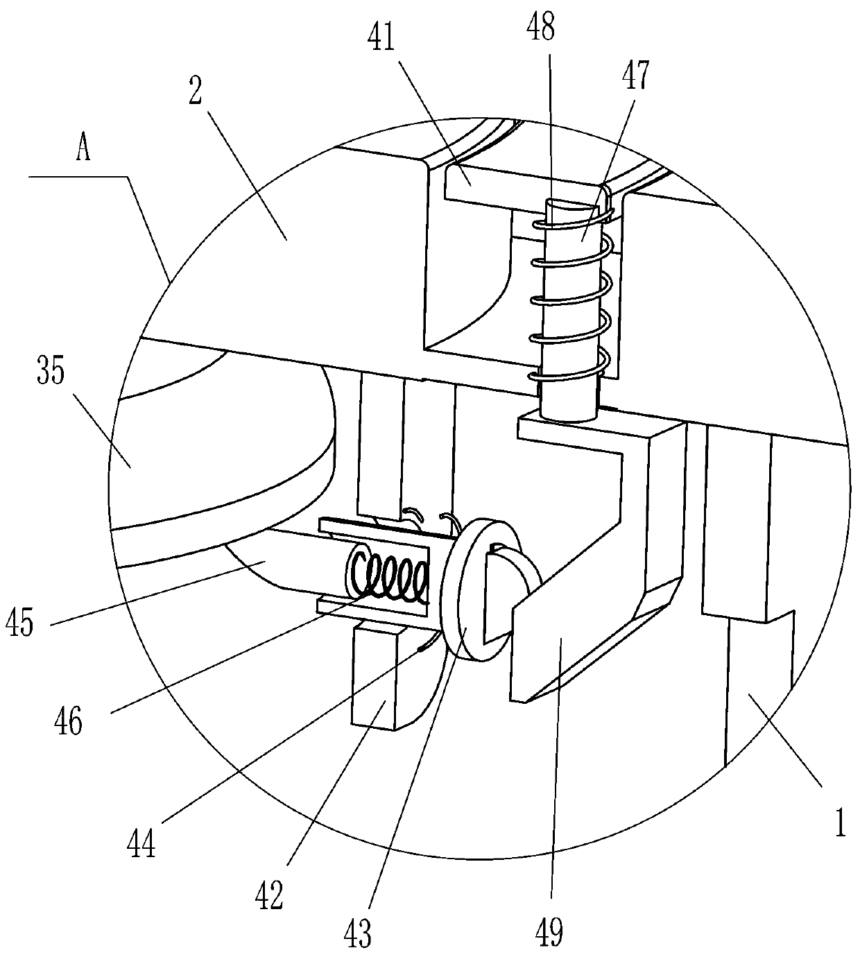
[0020] see figure 1 , figure 2 and Figure 4 , a hole reserved plugging device for construction engineering, including a shell 1, a grooved plate 2, a fixing mechanism 3 and a limit mechanism 4, the top of the shell 1 is fixedly connected with a grooved plate 2, and the grooved plate 2 is A limiting mechanism 4 is provided, and a fixing mechanism 3 is arranged on the housing 1 , and the fixing mechanism 3 cooperates with the limiting mechanism 4 .

[0021] Fixing mechanism 3 includes movable clamping lever 31, first spring 32, conical block 33, second spring 34 and first strong magnet 35, and the middle part of housing 1 front and back, left and right sides all slides and is provided with movable clamping lever 31, movable A first spring 32 is wound between the inside of the clamp rod 31 and the inner surface of the housing 1, and the middle part of the housing 1 is provided with a conical block 33. A second spring 34 is connected between the inner bottom of the housing 1 ...

Embodiment 2

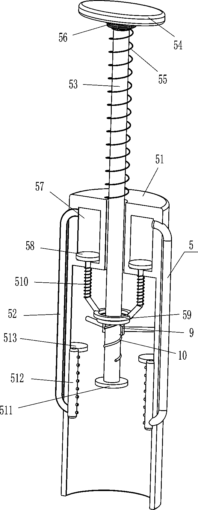
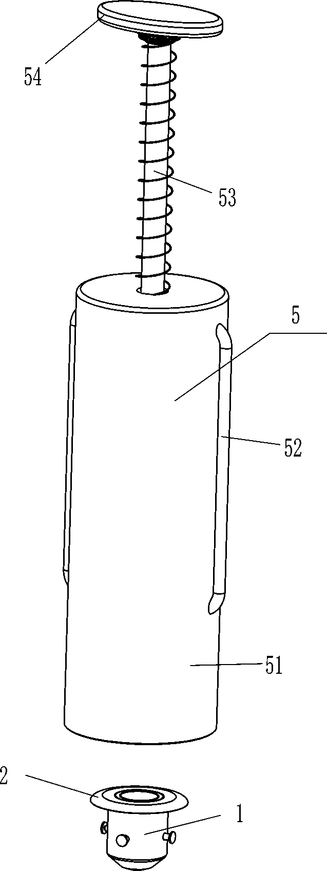
[0027] see figure 1 and image 3 Compared with Embodiment 1, the main difference of this embodiment is that in this embodiment, a clamping mechanism 5 is also included, and the clamping mechanism 5 includes a cylinder 51, a connecting pipe 52, a movable rod 53, a turning block 54, a sixth Spring 55, the first ring block 56, piston rod 58, the second ring block 59, the seventh spring 510, the second strong magnet 511, the jet pipe 512 and the fixed block 513, the middle sliding type of cylinder body 51 is provided with Movable rod 53, the top of movable rod 53 is connected with rotating block 54, the upper part of movable rod 53 is covered with first ring block 56, and the sixth spring is connected between the bottom of first ring block 56 and the outer top of cylinder body 51 55, the sixth spring 55 is sleeved on the movable rod 53, the bottom end of the movable rod 53 is fixedly connected with the second strong magnet 511, the lower part of the movable rod 53 is covered with...

Embodiment 3

[0030] see figure 2 and image 3 The main difference between this embodiment and embodiment 1 and embodiment 2 is that in this embodiment, a T-shaped bar 6 and an eighth spring 7 are also included. A T-shaped bar 6 is slidingly provided in the groove 8, and an eighth spring 7 is connected between the inner end of the T-shaped bar 6 and the inner surface of the chute 8 .

[0031] Also include nut 9, the movable rod 53 bottom has thread 10, the movable rod 53 bottom is provided with nut 9 through thread 10, and the outer surface of nut 9 is fixedly connected with cylinder body 51 inner surface top.

[0032] When the conical block 33 drives the movable clamping rod 31 to move outwards, the movable clamping rod 31 also drives the T-shaped rod 6 to move outwards, and the T-shaped rod 6 moves outwards to contact the inner wall of the hole. Due to the effect of the eighth spring 7, the T-shaped The rod 6 is always in contact with the inner wall of the hole. In this way, the movab...


PUM


Abstract

The invention relates to a plugging device, in particular to a hole reservation plugging device for construction engineering and aims to achieve the technical purpose of designing the hole reservationplugging device for construction engineering which can plug a hole well, is not kicked easily and is convenient to take out. The hole reservation plugging device for construction engineering comprises a shell and a fixing mechanism, wherein one side of the shell is fixedly connected with a slotted disc, and a groove in the slotted disc is annular; and the fixing mechanism is installed on the shell and used for fixing the shell in the hole. According to the hole reservation plugging device for construction engineering, by placing the shell into the hole and pushing an annular block to move downwards, a movable clamping block can be separated from a first strong magnet, a movable clamping rod can move outwards to make contact with the hole to fix the shell, so that the shell cannot be easily kicked by people, the situation that the shell is separated from the hole and using is affected is avoided, and the shell can be conveniently taken out of the hole through the action of a clamping mechanism.

Description

technical field [0001] The invention relates to a occluder, in particular to a hole reserved occluder for construction engineering. Background technique [0002] The Architectural Engineering major is mainly responsible for the teaching and management of the Architectural Engineering direction of the Civil Engineering major. It mainly cultivates and masters the basic theories and basic knowledge of engineering mechanics, soil mechanics, surveying, building architecture and structural engineering. Refers to the general designation of various buildings and engineering facilities that provide material and technological foundations for human life and production. During the construction of construction projects, there will be a large number of holes. Due to the large amount of impurities during the construction process, in order to prevent the impurities from falling into the holes and affecting the use, the holes will be blocked during construction, and the plugging tools will ...

Claims


Application Information

Patent Timeline
Patent Type & Authority Applications(China)
IPC IPC(8): E04G21/30
CPCE04G21/30
Inventor 廖志浓吴伟程
Owner 江西立丰新型材料科技有限公司
Why Eureka
Try Eureka