Friction and wear test device for variable load cylinder liner and piston ring

A friction and wear test, piston ring technology, applied in the direction of measuring devices, wear resistance testing, instruments, etc., can solve the problems of the occurrence of alternating loads and the inability to measure, the inability to realize continuous changes in loads, and the impact on the accuracy of measurement results, etc. , to achieve the effect of easy operation, reduced lever swing, and convenient operation

CN102288502AInactive Publication Date: 2011-12-21CHINA UNIV OF MINING & TECH
8 Cites 37 Cited by

Patent Information

Authority / Receiving Office
CN · China
Patent Type
Applications(China)
Current Assignee / Owner
Publication Date
2011-12-21
Estimated Expiration
Not applicable · inactive patent

Smart Images

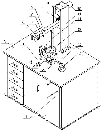
  • Figure 1
    Figure 1
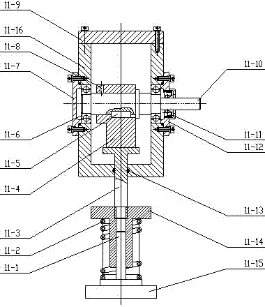
  • Figure 2
    Figure 2
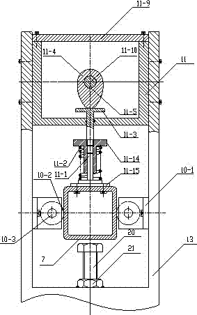
  • Figure 3
    Figure 3
Patent Text Reader

Abstract

A variable-load cylinder-sleeve piston-ring frictional wear testing device is mainly composed of a main shaft motor, a guide rail, a sliding table, left and right uprights, a work table, a lever, a loading rod, a swing limiter, a load changer, an inner concave cambered-surface lower clamp and an outer convex cambered-surface upper clamp. An alternating force is generated by the load changer, and then is amplified by the lever to act on a test piece, thereby realizing radial loading of a piston ring to a cylinder sleeve; a variable load is measured in real time by a pressure sensor between theload changer and the lever; friction is measured by a foil gauge on the loading rod; the swing amplitude of the lever is reduced by the swing limiter; the loading rod comes into contact with the outer convex cambered-surface upper clamp through a ball pair to guarantee that the loading direction is vertically downward; the rotating speed of the motor is controlled by means of a program so as to carry out frictional wear tests at different speeds. The testing device is simple in structure, various in testing functions and high in accuracy.
Need to check novelty before this filing date? Find Prior Art

Description

technical field

[0001] The invention relates to a variable load cylinder liner-piston ring friction and wear test device, which is especially suitable for testing the cylinder liner-piston ring friction and wear performance parameters of the engine under different working conditions. Background technique

[0002] Cylinder liner-piston ring is one of the most important friction pairs of the engine, and its friction and wear performance directly affects the performance of the engine. The radial pressure between cylinder liner and piston ring directly affects its friction and wear performance. For the engine cylinder liner-piston ring friction pair, its radial pressure changes periodically and continuously during the reciprocating stroke of the piston ring. The pressure curve is horizontal in the suction and exhaust strokes, and parabolic in the compression and power strokes, rising first and then falling. Therefore, one of the difficulties in the development of engine cylind...

Examples

Embodiment Construction

[0021] An embodiment of the present invention will be further described below in conjunction with accompanying drawing:

[0022] like figure 1 As shown, the variable load cylinder liner piston ring friction and wear test machine is mainly composed of a spindle motor 1, a guide rail 2, a slide table 3, a left column 4, a workbench 5, a lever 7, a loading rod 9, a swing limiter 10, and a load changer 11 , load-changing motor 12, right column 13, clamp 18 under the concave arc surface, and clamp 19 on the convex arc surface. Guide rail 2, slide table 3, left column 4, right column 13 are arranged on the workbench 5, and main shaft motor 1 is arranged in the workbench 5; Weight 15 on the weight hook, one side of slide table 3 is provided with connecting rod 16, and the outer end of connecting rod 16 is connected with crankshaft disk 17, and crankshaft disk 17 is connected with the spindle motor 1 that is located in the workbench 5 through the shaft. Connected, the slide table 3 ...