Refrigerator door shell end bending die

A bending mold and shell end technology, which is applied in the field of refrigerator door shell end bending molds, can solve the problems of scrapped appearance, complicated operation process, and low production efficiency, so as to reduce surface scratches, meet customer requirements, and reduce surface damage. wrinkled effect

Active Publication Date: 2011-03-09
滁州市科创模具制造有限公司
View PDF5 Cites 37 Cited by
  • Summary
  • Abstract
  • Description
  • Claims
  • Application Information

AI Technical Summary

Problems solved by technology

The traditional bending die is composed of an upper die and a lower die. In order to ensure the bending effect during bending, the traditional bending process is to cut a process gap (Germany) at the bending corner of the door shell, and cut to the root of the bending corner. There is a slight deviation in positioning during bending, and the incision is higher than the entire bending surface after bending, and sometimes the butt joint can be seen, resulting in scrapped appearance and high scrap rate. In addition to the scheme of cutting process gaps, there is also the scheme of folding the end on the plane first, and then folding the large surface, but this scheme has defects such as surface wrinkling and surface coating damage due to the accumulation of bending materials at the corner R. , the smaller the R angle, the more serious the defect, and the door shell cannot get a higher surface quality.
At the same time, since the surface of the refrigerator door shell is bent, there are also bending ends composed of large arc surfaces, small arc surfaces, inclined surfaces, vertical surfaces, etc. Insufficient processing of the bent end, and the simultaneous bending of the bent end composed of multiple surfaces such as a large arc surface, a small arc surface, an inclined surface, and a vertical surface cannot be realized. Therefore, each section after bending the end It is difficult to guarantee the consistency, the operation process is more complicated, and the production efficiency is relatively low

Method used


Image

  • Refrigerator door shell end bending die
  • Refrigerator door shell end bending die
  • Refrigerator door shell end bending die

Examples


Embodiment Construction

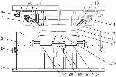
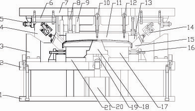
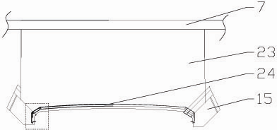
[0022] Such as figure 1 , figure 2 , image 3 As shown, the refrigerator door shell end bending mold of the present invention includes an upper template 7, a lower template 2, a mounting plate 1, a binder plate and a bending lower mold, and the binder plate includes a middle binder plate 11 and two The side binder plate 13 is connected to the upper template 7 through the spring assembly 8 and the guide column 9, and the middle bending module 23 is installed on the upper template 7, and its lower end surface corresponds to the upper surface of the middle binder plate 11, The middle bending module 23 is located in front of the middle holding plate 11 and is tangent to the front edge of the middle holding plate 11; the two sides of the upper template 7 are equipped with a hanging wedge mechanism, which includes an upper sliding slanting block 4 and the two side bending sliders 15 connected by the elastic connection mechanism 14, the elastic connection mechanism 14 is fixed on ...


PUM


Abstract

The invention discloses a refrigerator door shell end bending die. An upper die plate is provided with a middle bending die block, and a middle bending die block is positioned in front of a middle pressure plate and tangent to the edge of the front end of the middle pressure plate; both sides of the upper die plate are provided with a lewisson mechanism; each lewisson mechanism comprises an upper sliding tapered wedge and two side bending sliding blocks which are connected through an elastic connecting mechanism fixed on the upping sliding tapered wedge; a lower bending die comprises sliding blocks, which move horizontally on two sides, and a middle sliding block which moves up and down; and the sliding blocks, which move horizontally on two sides, are composed of two lower die spliced blocks and two lower die side sliding blocks which are fixed with the lower die spliced blocks. The refrigerator door shell end bending die can be used for bending the end to the root on the sheet composed of a plurality of cambered surfaces, planes and the like, and has the advantages of convenient operation and high production efficiency, so that the product can achieve good surface quality and satisfy the customer requirement.

Description

technical field [0001] The invention relates to a bending die for a refrigerator door shell end. [0002] Background technique [0003] The refrigerator door shell adopts the upper and lower end flanges, and the upper and lower end covers are inserted into the door shell flanges from the front direction of the door shell. There is no need to protrude a plastic side to cover the door shell, and the overall appearance is beautiful. The refrigerator door shell is an important part of the refrigerator, and its end bending process directly affects the appearance and performance of the refrigerator. The traditional bending die is composed of an upper die and a lower die. In order to ensure the bending effect during bending, the traditional bending process is to cut a process gap (Germany) at the bending corner of the door shell, and cut to the root of the bending corner. There is a slight deviation in positioning during bending, and the incision is higher than the entire bendin...

Claims


Application Information

Patent Timeline
Patent Type & Authority Applications(China)
IPC IPC(8): B21D37/10B21D37/12B21D5/06
Inventor 王和升张学丰
Owner 滁州市科创模具制造有限公司
Why Eureka
Try Eureka