Controller and control method of robot, and robot system
A robot system and control device technology, applied in the field of robot systems, can solve the problems of inability to teach and fit the robot, damage and change of the workpiece, etc.
- Summary
- Abstract
- Description
- Claims
- Application Information
AI Technical Summary
Problems solved by technology
Method used
Image

Examples
no. 1 approach
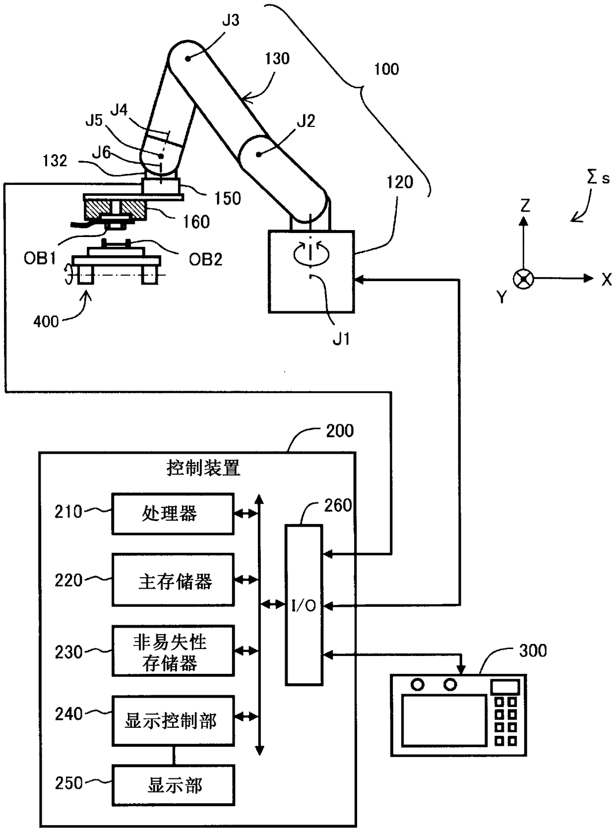
[0049] figure 1 is a schematic diagram of the robotic system of one embodiment. This robot system includes a robot 100 , a control device 200 , a teaching box 300 , and a transport device 400 . The robot 100 is a teaching reproduction type robot. Work using the robot 100 is executed in accordance with pre-generated teaching data. In this robot system, a system coordinate system Σs defined by three orthogonal coordinate axes X, Y, and Z is set. exist figure 1 In the example, the X-axis and Y-axis are in the horizontal direction, and the Z-axis is in the vertical direction. The teaching points included in the teaching data and the posture of the end effector are represented by the coordinate values of the system coordinate system Σs and the angles around each axis.
[0050] The robot 100 includes a base 120 and an arm 130 . The arm 130 is sequentially connected by six joints J1 to J6. Among these joints J1 to J6, three joints J2, J3, and J5 are bending joints, and the o...
no. 2 approach
[0085] Figure 15 It is a flowchart showing the teaching data generation procedure in the second embodiment, and is the same as that of the first embodiment. Figure 10 corresponding figure. Figure 16 It is an explanatory diagram showing the state of rotation of the object in the second embodiment. It should be noted that since the configuration of the robot system is the same as that of the first embodiment, description thereof will be omitted. The difference between the second embodiment and the first embodiment is only that steps S135 and S136 are added, and the other procedures are the same as those of the first embodiment.
[0086] When the teaching point search process ends in step S130 ( Figure 11 ), proceed to step S135, and judge whether all the searches have been completed. In the second embodiment, the search process for the teaching point is executed at a plurality of rotation angles around one or more axis directions. For example, regarding rotation of one ...
no. 3 approach
[0089] Figure 17 It is a flowchart showing the teaching data generation procedure in the third embodiment, and is the same as that of the second embodiment. Figure 15 corresponding figure. It should be noted that the configuration of the robot system is the same as that of the first embodiment and the second embodiment, so description thereof will be omitted. The difference between the third embodiment and the second embodiment is only that step S136 is replaced with step S138, and the other procedures are the same as those of the second embodiment.
[0090] When the point search process is taught in step S130 ( Figure 11 ) after the end, proceed to step S135, and judge whether all the explorations have been completed. In the third embodiment, when step S130 is executed for the first time, if the relative position at which the moving distance of the first object OB1 until contact is the longest is obtained, then the process proceeds from step S135 to S138, and the search...
PUM
 Abstract
Description
Claims
Application Information
 - R&D
- Intellectual Property
- Life Sciences
- Materials
- Tech Scout
- Unparalleled Data Quality
- Higher Quality Content
- 60% Fewer Hallucinations
Browse by: Latest US Patents, China's latest patents, Technical Efficacy Thesaurus, Application Domain, Technology Topic, Popular Technical Reports.
© 2025 PatSnap. All rights reserved.Legal|Privacy policy|Modern Slavery Act Transparency Statement|Sitemap|About US| Contact US: help@patsnap.com