Working method of bridge cable maintenance device

A technology for overhauling devices and working methods, applied in bridges, bridge parts, bridge construction, etc., can solve problems such as hidden safety hazards, hidden safety hazards of maintenance personnel, and cable maintenance, so as to reduce work risks, avoid climbing work, and reduce workload. Effect

Active Publication Date: 2018-11-23
绍兴金楚印染有限公司
View PDF7 Cites 5 Cited by
  • Summary
  • Abstract
  • Description
  • Claims
  • Application Information

AI Technical Summary

Problems solved by technology

[0002] Cables are an important part of large-scale bridges. Cables are also key stress-bearing parts of bridges. One type of cable spans a relatively large length and height. Manual maintenance is not only time-consuming and laborious, but also has potential safety hazards. Therefore, there are A variety of cable automatic detection devices, Chinese Patent No. CN102323331B discloses an in-service cable defect detection device for detecting internal defects in cables. There are multiple detection modules in the circumferential direction, and the two ends of each detection module are respectively clamped together by the external frame set on the cable; the detection module is a modular design, consisting of a magnetized adsorption unit, an active unit, a driven unit and a detection probe unit ; The detection crawler moves along the cable by climbing on the surface to obtain the internal detection signal of the cable, and transmits it to the signal processing part for analysis and processing to complete the detection of the cable
This patent explains in detail how to detect the cable, but the device cannot repair the cable. Generally, if the PE protective tube outside the cable is slightly damaged, it is only necessary to wrap a heat shrinkable tape on its outer surface. It is cumbersome to erect a lifting device on the bridge through manual winding, and it will increase the workload of maintenance personnel and bring safety hazards to maintenance personnel

Method used


Image

  • Working method of bridge cable maintenance device
  • Working method of bridge cable maintenance device
  • Working method of bridge cable maintenance device

Examples


Embodiment Construction

[0031] The following will be combined with Figure 1 to Figure 11 The present invention is described in detail, and the technical solutions in the embodiments of the present invention are clearly and completely described. Apparently, the described embodiments are only some of the embodiments of the present invention, not all of them. Based on the embodiments of the present invention, all other embodiments obtained by persons of ordinary skill in the art without making creative efforts belong to the protection scope of the present invention.

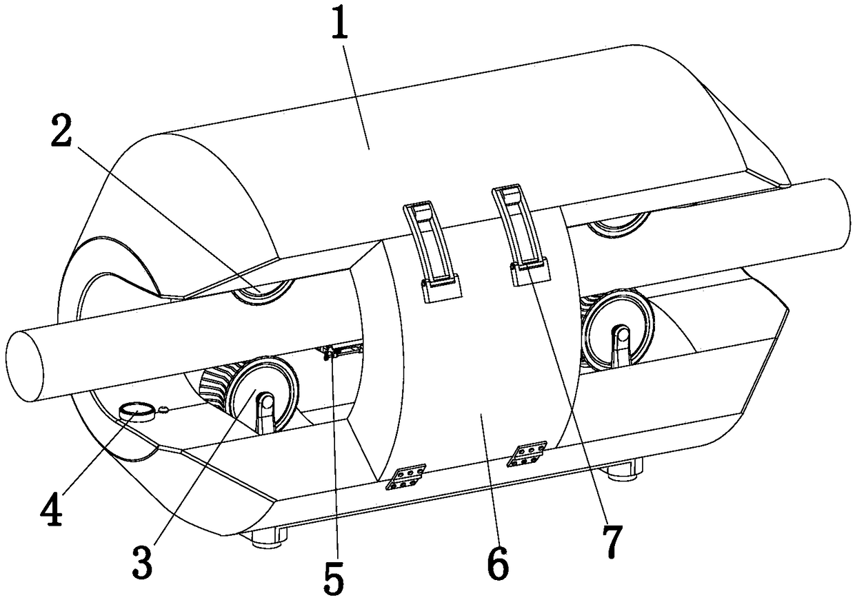
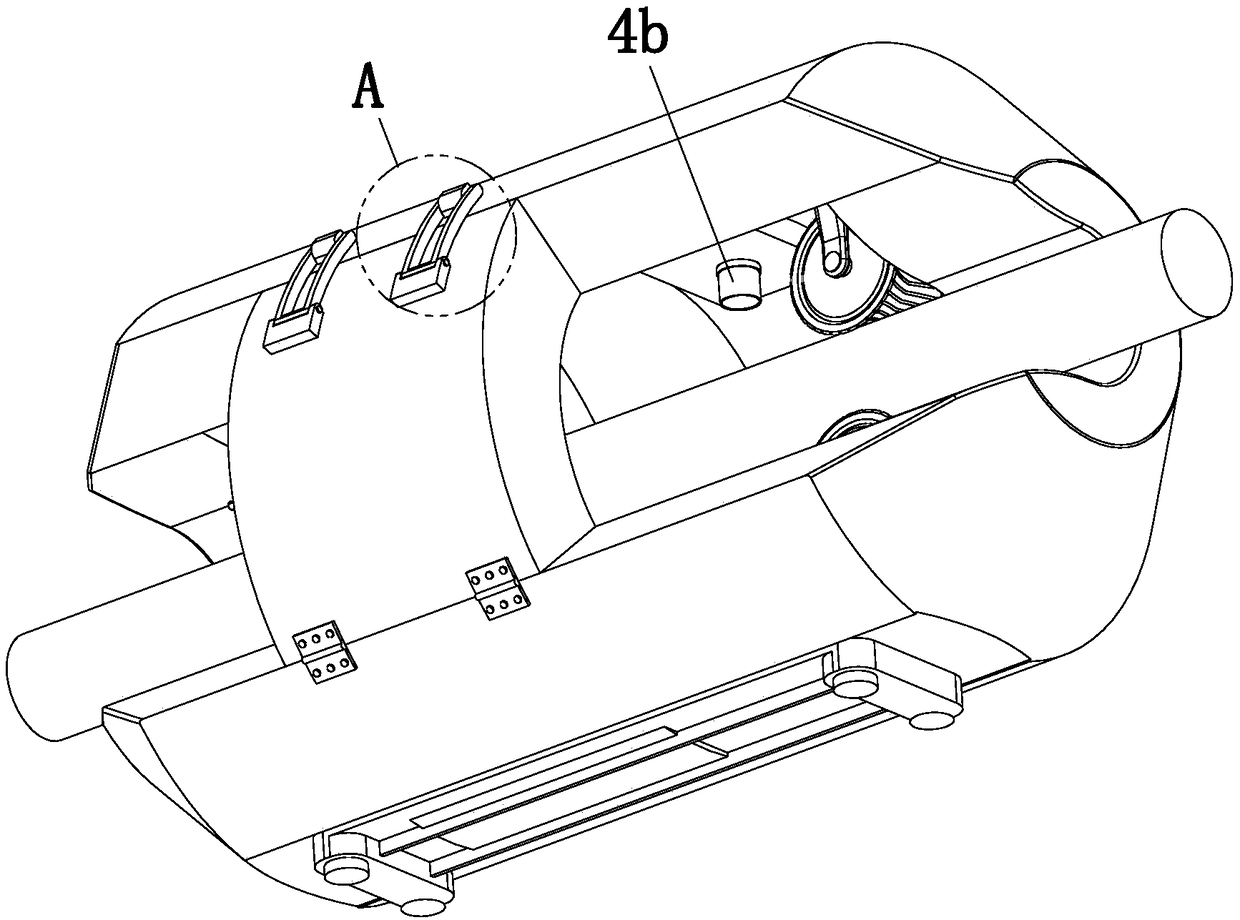
[0032] The present invention provides a kind of working method of bridge cable maintenance device here by improving, as Figure 1-Figure 11 Shown, comprise car body 1, moving mechanism 2, pressing mechanism 3, detection mechanism 4 and winding mechanism 5, described moving mechanism 2, pressing mechanism 3 and winding mechanism 5 are all installed in the middle part of car body 1, described The pressing mechanism 3 is located directly be...


PUM


Abstract

The invention relates to the field of bridge detection, in particular to a working method of a bridge cable maintenance device. The device comprises a cart, a movable mechanism, a pressing mechanism,a detection mechanism and a winding mechanism, the movable mechanism, the pressing mechanism and the winding mechanism are mounted in the middle of the cart, the pressing mechanism is positioned belowthe movable mechanism, the detection mechanism comprises a first detection component and a second detection component, the first detection component and the second detection component are mounted inthe front and the rear of the cart, the winding mechanism comprises a rotating component, a pressing and pasting component and a feeding component, the feeding component and the pressing and pasting component are mounted on the rotating component, the rotating component is positioned in the middle of the cart, a notch is formed in one side of the cart, and a first storage battery is arranged in the middle of the cart and used for supplying power for the detection mechanism and the movable mechanism. The device has the advantages that the outside and the inside of a cable can be detected, and outside damage to the cable can be automatically repaired.

Description

technical field [0001] The invention relates to the field of bridge detection, in particular to a working method of a bridge cable maintenance device. Background technique [0002] Cables are an important part of large-scale bridges. Cables are also key stress-bearing parts of bridges. One type of cable spans a relatively large length and height. Manual maintenance is not only time-consuming and laborious, but also has potential safety hazards. Therefore, there are A variety of cable automatic detection devices, Chinese Patent No. CN102323331B discloses an in-service cable defect detection device for detecting internal defects in cables. There are multiple detection modules in the circumferential direction, and the two ends of each detection module are respectively clamped together by the external frame set on the cable; the detection module is a modular design, consisting of a magnetized adsorption unit, an active unit, a driven unit and a detection probe unit The detectio...

Claims


Application Information

Patent Timeline
IPC IPC(8): E01D19/10
CPCE01D19/106
Inventor 杨帆段建锋李宁
Owner 绍兴金楚印染有限公司
Why Eureka
Try Eureka