
Built-in lead pin type tension-compression and rotation combined damper

A damper and lead pin technology, which is used in protective buildings/shelters, building components, earthquake-proof and other directions, can solve the problem that the material yield dispersion area is not large enough, the energy dissipation structure design is not very sufficient, and the initial stiffness of the damper is not large enough. and other problems, to achieve the effect of reducing seismic response, large initial stiffness, and large yield area

Inactive Publication Date: 2018-11-23
SHENYANG JIANZHU UNIVERSITY
View PDF0 Cites 0 Cited by
  • Summary
  • Abstract
  • Description
  • Claims
  • Application Information

AI Technical Summary

Problems solved by technology

[0003] At present, the initial stiffness of many dampers is not large enough, the yield dispersion area of ​​the material is not large enough, and the design of the energy-dissipating structure is not very sufficient, so that the energy such as kinetic energy or elastic potential energy of the structure cannot be fully converted into heat energy and dissipated. Many dampers are only It can increase the overall stiffness of the building structure during normal use, but when a large earthquake occurs, many dampers cannot meet the requirements of reducing the seismic response of the building structure

Method used


Image

  • Built-in lead pin type tension-compression and rotation combined damper
  • Built-in lead pin type tension-compression and rotation combined damper
  • Built-in lead pin type tension-compression and rotation combined damper

Examples


Embodiment

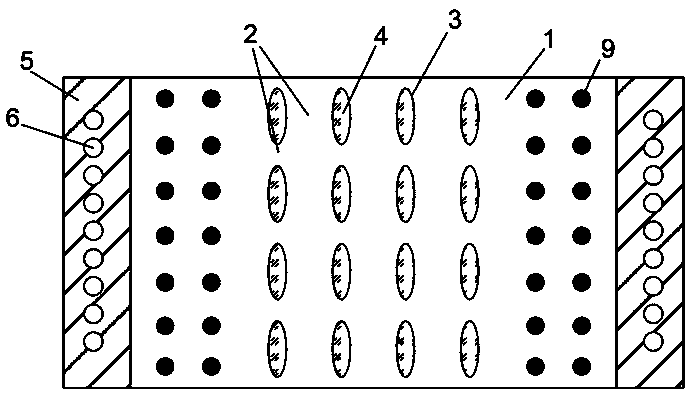
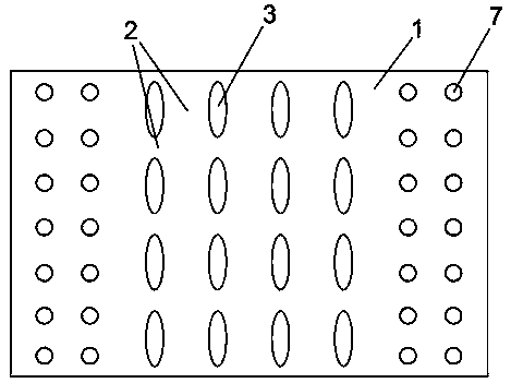
[0023] A built-in lead pin type tension-compression and rotation combined damper, such as Figure 1~Figure 6 As shown, it includes energy-dissipating steel plates 1 with elliptical holes inside, energy-dissipating ribs 2, elliptical holes inside 3, viscoelastic friction energy-dissipating pads 4, connecting plates 5, connecting plate screw holes 6, lead pin holes 7, pull Pressure friction energy-dissipating steel plate 8, lead pin 9, circular extruded friction energy-dissipating soft steel plate 10 and rotation reserved space 11, in the structure of built-in lead pin type tension-compression and rotation combined damper, the upper and lower parts are respectively equipped with internal devices. An energy-dissipating steel plate 1 with elliptical holes, a viscoelastic friction energy-dissipating backing plate 4 is arranged on the inner side of the energy-dissipating steel plate 1 with an elliptical hole, and a circular extrusion is arranged in the middle between the two viscoela...


PUM


Abstract

The invention provides a built-in lead pin type tension-compression and rotation combined damper, belonging to the field of vibration control of building structures. The upper and lower sides of the built-in lead pin type tension-compression and rotation combined damper are provided with energy dissipation steel plates with elliptical holes inside respectively, the inner sides of the energy dissipation steel plates with the elliptical holes are provided with viscoelastic friction energy dissipation pads, a circular extrusion friction energy dissipation mild steel plate is arranged in the middle between the two viscoelastic friction energy dissipation pads, tension-compression friction energy dissipation steel plates are symmetrically arranged on the left and right sides of the circular extrusion friction energy dissipation mild steel plate, a rotation reserved gap is formed between the tension-compression friction energy dissipation steel plates, a connecting plate is arranged on one side of each tension-compression friction energy dissipation steel plate and is provided with a connecting plate screw hole, and multiple rows of lead pin holes are formed in one side, close to the corresponding connecting plate, of each tension-compression friction energy dissipation steel plate. The built-in lead pin type tension-compression and rotation combined damper has the beneficial effectsof large initial rigidity, large steel yielding area and good energy dissipation effect, and can reduce the seismic response of a building structure.

Description

technical field [0001] The invention belongs to the field of vibration control of building structures, in particular to a built-in lead pin type pull-compression and rotation combined damper. Background technique [0002] Metallic yielding dampers are various forms of damping energy dissipators made of mild steel or other soft metal materials. Metals have good hysteretic properties after yielding, and some metals have elastic-plastic hysteretic deformation energy dissipation, including mild steel dampers, lead dampers, and shape memory alloys (SMA) dampers. The mechanism of its vibration control on the structure is to dissipate part of the energy of the structure vibration through the yield hysteresis energy consumption of the metal, so as to reduce the structural response. The mild steel damper is to make full use of the soft steel after entering the plastic stage Good hysteresis characteristics. In 1972, American scholars such as Kelly and Skinner first began to study th...

Claims


Application Information

Patent Timeline
IPC IPC(8): E04B1/98E04H9/02
CPCE04H9/021
Inventor 张延年杨森
Owner SHENYANG JIANZHU UNIVERSITY
Learn More