Identification method and system of impulsive noise in power line communication system

A power line communication and impulse noise technology, applied in the field of noise identification, can solve the problems that the statistical characteristics of impulse noise cannot represent the actual situation and the mutual influence of signals

Inactive Publication Date: 2018-11-23
GUANGDONG UNIV OF PETROCHEMICAL TECH
View PDF3 Cites 7 Cited by
  • Summary
  • Abstract
  • Description
  • Claims
  • Application Information

AI Technical Summary

Problems solved by technology

In this way, due to the mutual influence between signals, the obtained statis

Method used


Image

  • Identification method and system of impulsive noise in power line communication system
  • Identification method and system of impulsive noise in power line communication system
  • Identification method and system of impulsive noise in power line communication system

Examples


Embodiment 1

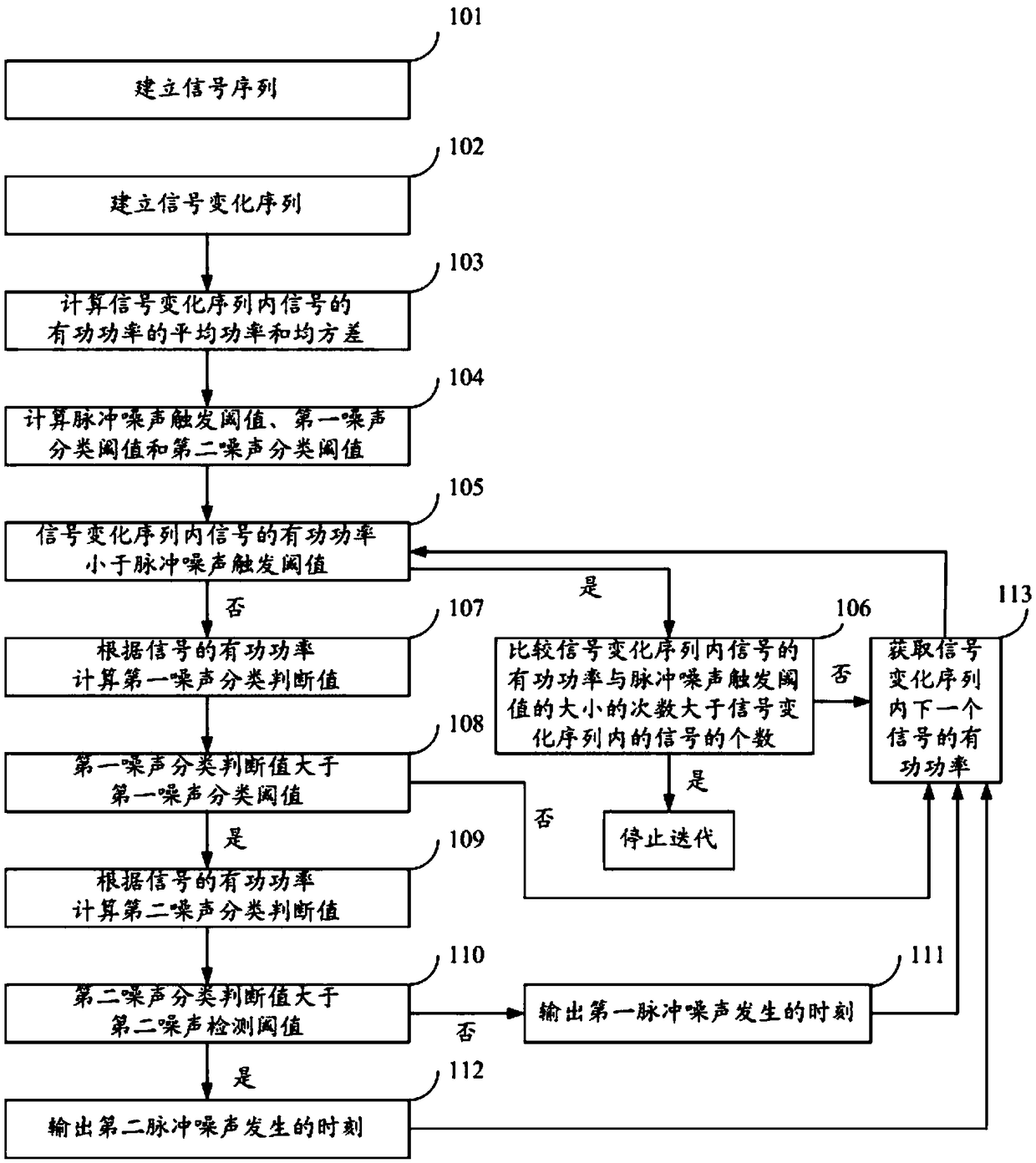
[0074] figure 1 It is a flowchart of a method for identifying impulse noise in a power line communication system in an embodiment of the present invention, as shown in figure 1 As shown, the identification method of impulse noise in the power line communication system includes:

[0075] Step 101: Establish a signal sequence.

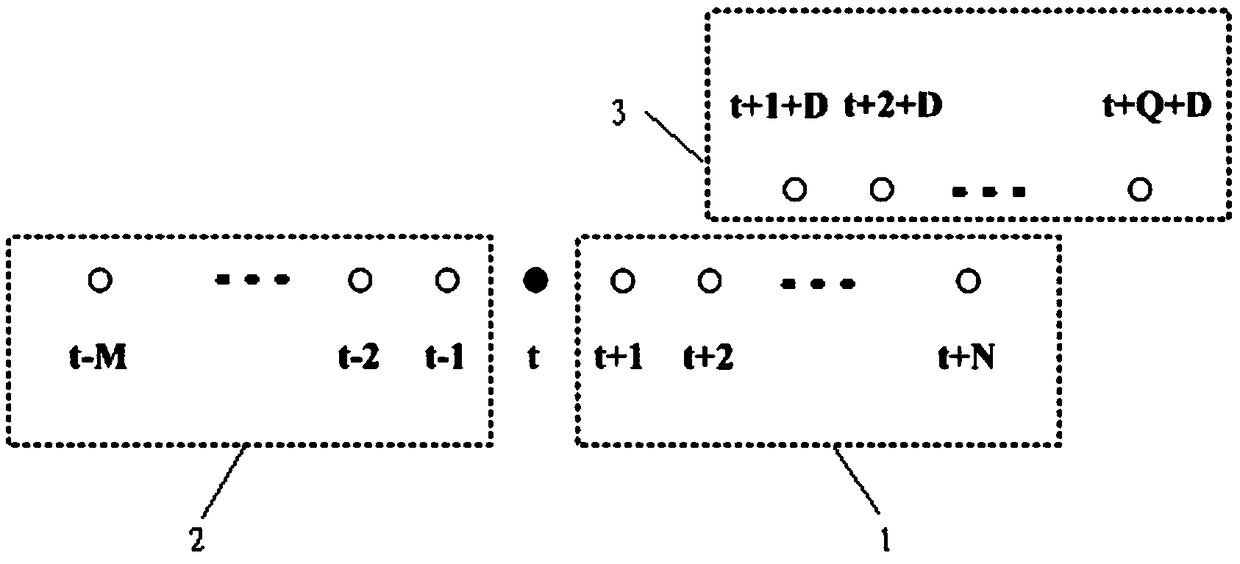
[0076] Acquiring the received power line communication signals, selecting a plurality of power line communication signals of the same number before and after the power line communication signals, and establishing a signal sequence according to the time sequence of the received power line communication signals;

[0077] Step 102: Establish a signal change sequence.

[0078] Obtain the signal amplitude of each signal in the signal sequence, and calculate the signal amplitude difference between two adjacent signals; select the power line communication signal corresponding to the adjacent signal amplitude difference that satisfies the preset difference thr...

Embodiment 2

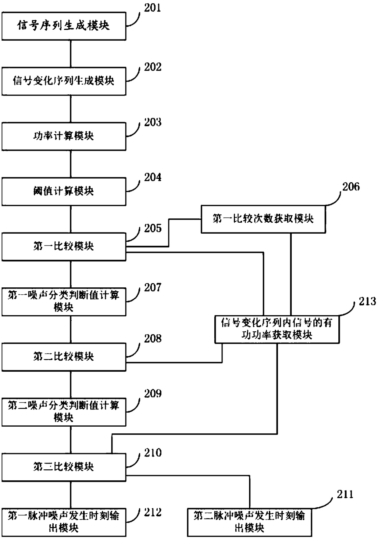
[0118] image 3 It is a structural diagram of the identification system of impulse noise in the power line communication system in the embodiment of the present invention, as shown in image 3 As shown, the identification system of impulse noise in the power line communication system includes:

[0119] The signal sequence generation module 201 is used to obtain the received power line communication signal, select a plurality of power line communication signals of the same number before and after the power line communication signal, and establish a signal sequence according to the time sequence of the received power line communication signal.

[0120] The signal change sequence generation module 202 is used to obtain the signal amplitude of each signal in the signal sequence, and calculate the signal amplitude difference between two adjacent signals; select the adjacent signal amplitude difference that satisfies the preset difference threshold The power line communication sign...


PUM


Abstract

The invention discloses the identification method and system of an impulsive noise in a power line communication system. The method comprises the following steps of establishing a signal sequence; establishing a signal change sequence; calculating the average power and the mean square error of the active power of a signal in the signal change sequence; calculating an impulse noise trigger threshold, a first noise classification threshold, and a second noise classification threshold; comparing the active power of the signal in the signal change sequence with the impulse noise trigger threshold;comparing a first noise classification determination value with the first noise classification threshold; comparing a second noise classification determination value with the second noise classification threshold; and outputting a moment when a first impulse noise is generated and a moment when a second impulse noise is generated. By using the method and the system of the invention, a long-pulsenoise and a short-pulse noise can be directly and accurately identified and extracted from power line communication modulation signals, and mutual influences among the signals can be well avoided.

Description

technical field [0001] The invention relates to the technical field of noise identification, in particular to a method and system for identifying impulse noise in a power line communication system. Background technique [0002] Power line communication technology is divided into narrowband power line communication and broadband power line communication. Narrowband power line communication refers to the power line carrier communication technology with a bandwidth limited to 3k ~ 500kHz. Narrowband power line communication technology mostly uses single carrier modulation technology, such as PSK technology, DSSS technology and chirp technology, and the communication rate is less than 1Mbits / s. Broadband power line communication technology refers to the power line carrier communication technology with a bandwidth limited between 1.6-30MHz and a communication rate usually above 1Mbps. It adopts a variety of spread spectrum communication technologies with OFDM as the core. [000...

Claims


Application Information

Patent Timeline
IPC IPC(8): H04B3/54
CPCH04B3/542H04B2203/5404H04B2203/5425
Inventor 翟明岳
Owner GUANGDONG UNIV OF PETROCHEMICAL TECH
Why Eureka
Try Eureka