Real-time QRS-wave detection method for electrocardiosignals

A technology of ECG signal and detection method, which is applied in diagnostic recording/measurement, medical science, sensors, etc. It can solve problems such as long learning and training time of algorithms, QRS wave distortion, and large amount of calculation, so as to overcome interference and improve accuracy. Accurate, real-time effect

Active Publication Date: 2018-11-27
NANJING UNIV
View PDF4 Cites 11 Cited by
  • Summary
  • Abstract
  • Description
  • Claims
  • Application Information

AI Technical Summary

Problems solved by technology

Among them, the algorithm principle of the differential threshold method is simple, the calculation amount is small, the real-time performance is good, and it is easy to implement in hardware. It is easily affected by large T waves, myoelectric interference and high-frequency artifacts; the filter combination used by the mathematical morphology method is simple, the calculation speed is fast, and the real-time performance is good, but it is easy to make the QRS wave when filtering out high-frequency noise. Distortion occurs, and the accuracy rate is not high; although the wavelet transform has a high detection accuracy rate, the calculation amount is relatively large, and it requires high-performance hardware support, which is not suitable for real-time monitoring of wearable devices; the neural network method has self-learning and self-adaptive Although good discrimination results can be obtained, the algorithm takes a long time to learn and train, and the amount of calculation is too large, so it is difficult to apply to real-time detection

Method used


Image

  • Real-time QRS-wave detection method for electrocardiosignals
  • Real-time QRS-wave detection method for electrocardiosignals
  • Real-time QRS-wave detection method for electrocardiosignals

Examples


Embodiment Construction

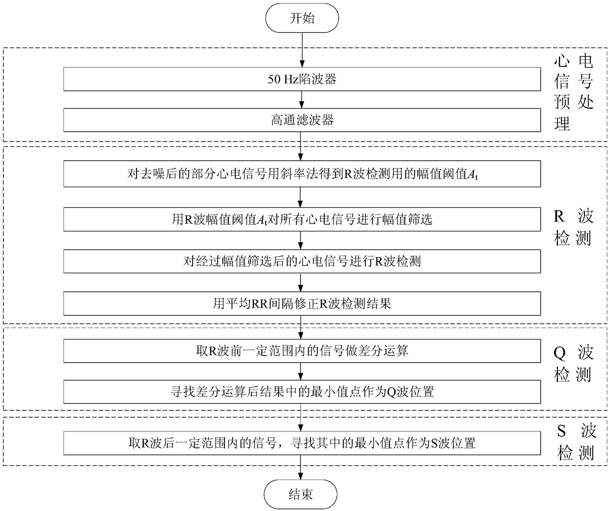
[0053] like figure 1 Described flow chart, a kind of electrocardiographic signal real-time QRS wave detection method provided by the present invention, comprises the following steps:

[0054] Step 1, the electrocardiographic signal is preprocessed to obtain the data of the denoised electrocardiographic signal, and the data includes a plurality of cycles;

[0055] Step 2, R wave detection, using the slope method to detect the R wave on the denoised ECG signal, and using the average RR interval to correct the detection result to obtain the position and amplitude of the R wave;

[0056] Step 3, Q wave detection, adopting the differential method to detect the position and amplitude of the Q wave according to the position of the R wave;

[0057] Step 4, S-wave detection, using the minimum value method to detect the position and amplitude of the S-wave according to the position of the R-wave.

[0058] The data used in this example is collected through a single-lead wearable sports...


PUM


Abstract

The invention relates to a real-time QRS-wave detection method for electrocardiosignals. The method comprises the following steps of 1, preprocessing the electrocardiosignals to obtain data of the denoised electrocardiosignals; 2, conducting R-wave detection, wherein part of the denoised electrocardiosignals is subjected to a slope method to obtain an amplitude threshold value At for R-wave detection, then the R-wave amplitude threshold value At is utilized for conducting amplitude sifting on all the electrocardiosignals, the electrocardiosignals which are subjected to amplitude sifting are subjected to R-wave detection, and an R-wave detection result is corrected through average RR intervals; 3, conducting Q-wave detection, wherein signals within a certain range before R waves are taken for differential operation, and the minimum value point in the result after the differential operation is searched for to serve as a Q-wave position; 4, conducting S-wave detection, wherein signals within a certain range after the R waves are taken, and the minimum value point in the result is searched for to serve as an S-wave position. By means of the method, QRS waves in the electrocardiosignalscan be quickly and effectively detected in real time, and the method is suitable for real-time QRS wave detection of wearable electrocardiogram monitoring equipment.

Description

technical field [0001] The invention relates to a real-time QRS wave detection method of an electrocardiogram signal. Background technique [0002] Cardiovascular disease is one of the main diseases that endanger human health today, and electrocardiography is an important method for clinical diagnosis of cardiovascular disease. Parameter extraction and waveform identification of ECG signal are the key to ECG signal analysis and diagnosis, and its accuracy and reliability determine the effect of diagnosis and treatment of heart disease patients. The detection of QRS complex is the basis of ECG signal analysis, and the accuracy of QRS complex location directly affects the correctness of subsequent processing. [0003] In cardiovascular health monitoring, wearable ECG monitoring equipment can continuously monitor the user's heart for a long time, which is convenient and effective to provide important ECG signal basis in the user's disease risk period, and provides medical pers...

Claims


Application Information

Patent Timeline
Patent Type & Authority Applications(China)
IPC IPC(8): A61B5/0402A61B5/0472A61B5/366
CPCA61B5/316A61B5/366A61B5/318
Inventor 张丽敏顾秀秀杨小伍丁健文
Owner NANJING UNIV
Why Eureka
Try Eureka