LED Lamp assembly apparatus

A technology for assembly equipment and LED lights, which is applied in metal processing equipment, metal processing, manufacturing tools, etc., can solve the problems of low efficiency and low assembly efficiency of assembly equipment, and achieve the effect of improving material receiving efficiency and assembly efficiency

Inactive Publication Date: 2018-11-27
韦美芬
5 Cites 3 Cited by

AI-Extracted Technical Summary

Problems solved by technology

It is also because the loading device and the unloading device in the assembly equipment retain the tradition...

Method used

The plastic manipulator a6 provided by the present embodiment, the fixed plate a68 is located at an end of the second slider plate a66, the fixed plate a68 and the second slider plate a66 are L-shaped; the second slider cylinder a67 connects the second The other end of the slider plate a66. In this embodiment, the air gripper a69 on the fixed plate a68 and the second slider cylinder a67 are arranged at both ends of the second slider plate a66. The stroke of the second slider cylinder a67 and the second slider plate a66 can be shortened, thereby making the structure of the plastic parts manipulator a6 more compact.
The positioning turntable mechanism b provided by the present embodiment also includes a fourth bottom plate b7, a vertical plate b8, a third cylinder b9, a thimble limiting block b10, and a thimble limiting groove b51 located on the periphery of the turntable plate b5 The third cylinder b9 is set on the fourth bottom plate b7 through the vertical plate b8; the thimble limit block b10 is connected to the third cylinder b9, and is driven by the third cylinder b9 to cooperate with the thimble limit groove b51. In this embodiment, the position of the turntable plate b5 can be locked by cooperating with the third cylinder b9, the thimble stop b...

Abstract

The invention provides an LED lamp assembly apparatus, comprising a positioning turnplate mechanism, and a plastic parts feeding mechanism, a plastic parts detection mechanism, an LED fitting mechanism and a product collecting mechanism which are arranged sequentially around the positioning turnplate mechanism. The plastic parts feeding mechanism comprises a plastic parts magnetic vibrator, a plastic parts first guide bar, a plastic parts second guide bar, a plastic parts limiter block, and a flexible connection block; the product collecting mechanism includes a mounting plate, a slide rail, afirst position sensor, a second position sensor, a third position sensor, a multi-level output cylinder, a collecting claw, and a pressure sensor. The LED lamp assembly apparatus can provide higher assembly efficiency.

Application Domain

Technology Topic

Image

  • LED Lamp assembly apparatus
  • LED Lamp assembly apparatus
  • LED Lamp assembly apparatus

Examples

  • Experimental program(1)

Example Embodiment

[0026] The above and other technical features and advantages of the present invention will be clearly and completely described below in conjunction with the accompanying drawings. Obviously, the described embodiments are only part of the embodiments of the present invention, rather than all the embodiments.
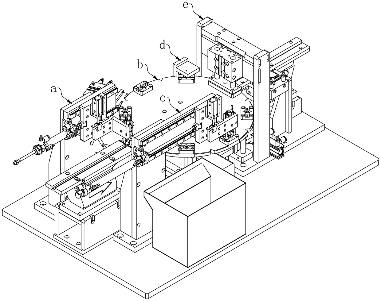
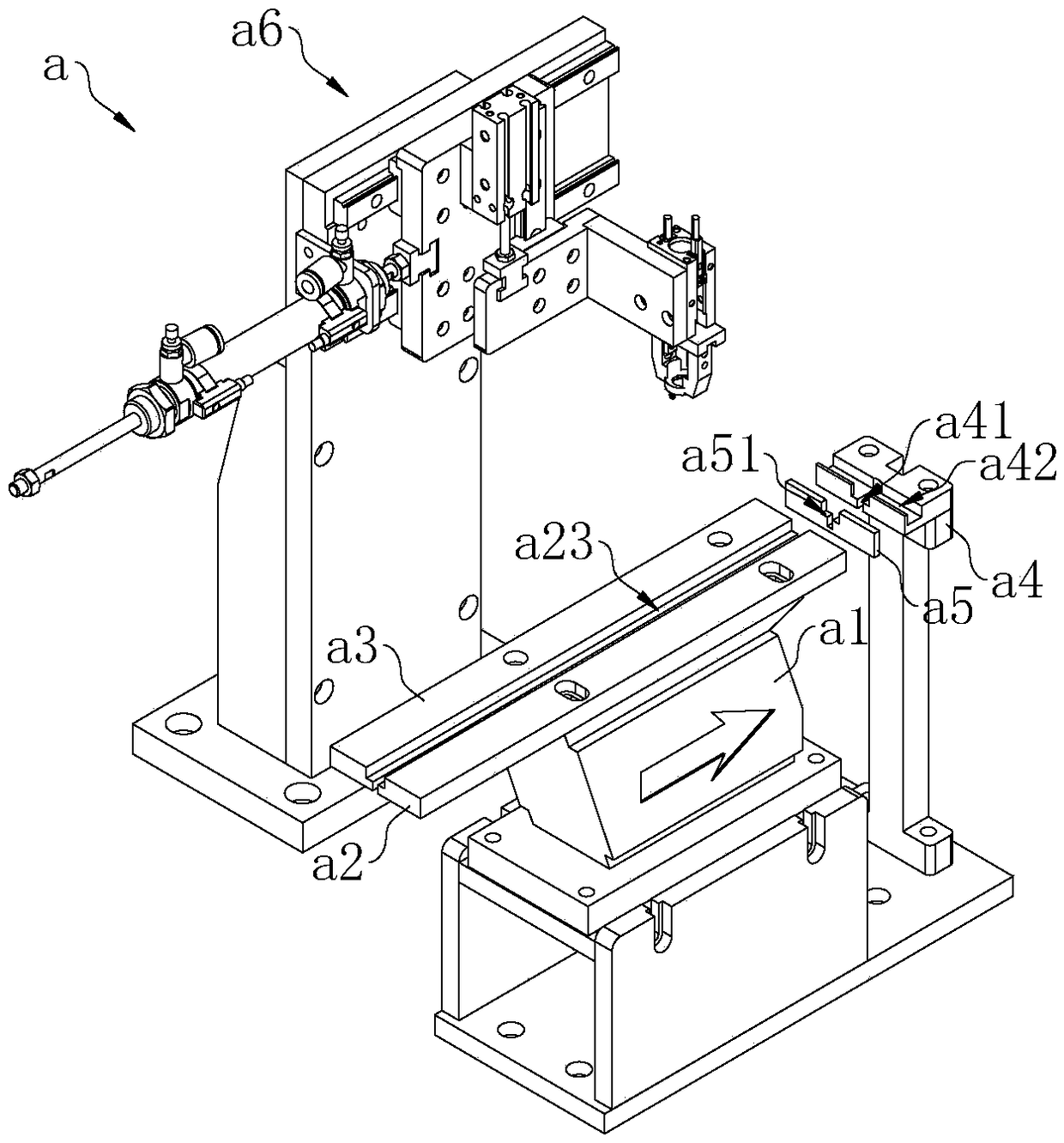
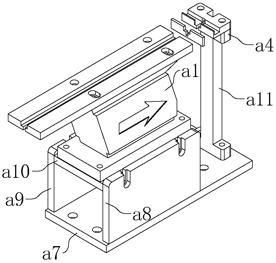
[0027] In one embodiment, such as figure 1 , figure 2 ,as well as Image 6 Shown.
[0028] The LED lamp assembly equipment provided in this embodiment includes a positioning turntable mechanism b, a plastic part feeding mechanism a, a plastic part detection mechanism d, a lamp bead assembly mechanism e, and a finished product receiving mechanism c that are sequentially arranged around the positioning turntable mechanism b; The plastic part feeding mechanism a includes a plastic part magnetic shock a1, a plastic part first guide bar a2, a plastic part second guide bar a3, a plastic part limit block a4, and a flexible connecting block a5; a plastic part first guide bar a2 and a plastic part There is a T-shaped guide bar channel a23 between the second guide bars a3; the plastic limit block a4 is located in the extending direction of the guide bar channel a23, and includes a cross-shaped T-shaped limit block channel a41 and an in-line reclaiming channel a42; the flexible connecting block a5 is connected between the guide bar channel a23 and the plastic limit block a4, and includes a T-shaped connection block channel a51; the guide bar channel a23, the connection block channel a51, and the limit block channel a41 are all in one word Arranged in sequence, the bottom of the guide channel a23 and the limit block channel a41 are through, and the bottom of the connecting block channel a51 is not through; the finished product receiving mechanism c includes a mounting plate c2, a sliding rail c3, a first position sensor c4, and a second position sensor c5, third position sensor c6, multi-stage output cylinder c7, receiving gripper c8, and pressure sensor c9; mounting plate c2 provides sliding rail c3, first position sensor c4, second position sensor c5, and third position sensor c6 , And the installation of the multi-stage output cylinder c7; the two ends close to the slide rail c3 are respectively provided with a first position sensor c4 and a third position sensor c6, and the middle of the slide rail c3 is provided with a second position sensor c5; c7 is used to drive the receiving jaw c8; the pressure sensor c9 is used to feed back the clamping force provided by the receiving jaw c8.
[0029] In this embodiment, the plastic part feeding mechanism a is used to convey plastic parts, the plastic part detection mechanism d is used to detect plastic parts, and the lamp bead assembly mechanism e is used to convey lamp beads and assemble the lamp beads and plastic parts, and the finished product receiving mechanism c is used to receive finished products. The LED lamp assembly equipment provided in this embodiment has high assembly efficiency, which is mainly reflected in the following two aspects. In the first aspect, in the plastic part feeding mechanism a, the T-shaped guide bar channel a23, the T-shaped connecting block channel a51, and the T-shaped limit block channel a41 are all customized according to the original structure of the plastic part. In order to meet the conveying speed of the plastic parts, the customized T-shaped guide bar channel a23 and T-shaped stop block channel a41 through the bottom can also achieve the purpose of positioning and conveying the plastic part to cooperate with the plastic part manipulator a6 for quick clamping and picking. During operation, the plastic part magnetic shock a1 provides power for the plastic part to be transported along the linear path arranged by the guide bar channel a23, the connecting block channel a51, and the limit block channel a41 through vibration. This is a conventional and mature way of providing power in the field of automation. However, in this embodiment, the first guide bar a2 of the plastic part, the second guide bar a3 of the plastic part, and the stop block a4 of the plastic part are separated by the flexible connecting block a5. The plastic part is protected from the magnetic shock a1 of the plastic part during the quick clamping process of the plastic part manipulator a6. Moreover, compared with the traditional method of separating the plastic first guide bar a2, the second plastic guide bar a3, and the plastic limit block a4, the method provided in this embodiment can achieve a highly stable conveying path to match The plastic part manipulator a6 quickly grips and picks up, which improves the conveying efficiency of the plastic part feeding mechanism a. In the second aspect, in the finished product receiving mechanism c, the first position sensor c4, the second position sensor c5, the third position sensor c6, and the pressure sensor c9 are used to cooperate with the multi-stage output cylinder c7 to improve the efficiency of receiving the finished product. . Specifically, when the receiving jaw c8 moves from the position of the first position sensor c4 or the third position sensor c6 to the position of the second position sensor c5, the multi-stage output cylinder c7 is connected to the first set air pressure; When the receiving jaw c8 moves from the position of the second position sensor c5 to the position of the first position sensor c4 or the third position sensor c6, the multi-stage output cylinder c7 is connected to the second setting less than the first setting air pressure Air pressure. When the receiving jaw c8 moves from the position of the first position sensor c4 to the position of the second position sensor c5, the receiving jaw c8 moves toward the positioning turntable mechanism b. And because it is connected to the first set air pressure, the movement speed is faster. When the receiving jaw c8 moves from the position of the second position sensor c5 to the position of the third position sensor c6, the receiving jaw c8 still moves toward the positioning turntable mechanism b. And because of the access to the second set air pressure, the movement speed is slow. Among them, in the two strokes from the first position sensor c4 to the second position sensor c5 and from the second position sensor c5 to the third position sensor c6, there is a speed change process, which can shorten the sum of the two stroke times. Correspondingly, when the receiving jaw c8 moves from the position of the third position sensor c6 to the position of the second position sensor c5, the receiving jaw c8 moves behind the positioning turntable mechanism b. And because it is connected to the first set air pressure, the movement speed is faster. When the receiving jaw c8 moves from the position of the second position sensor c5 to the position of the first position sensor c4, the receiving jaw c8 still moves with the positioning turntable mechanism b behind its back. And because of the access to the second set air pressure, the movement speed is slow. Among them, in the two strokes from the third position sensor c6 to the second position sensor c5 and from the second position sensor c5 to the first position sensor c4, there is a speed change process, which can shorten the sum of the two stroke times. In addition, the above speed change process needs to be established on the basis that the material receiving jaw c8 has sufficient clamping force. It can improve the efficiency of the finished product collection on the basis of preventing the collection jaw c8 from falling off. And in a preferred embodiment, the air pressure values ​​of the first set air pressure and the second set air pressure are positively correlated with the feedback value of the pressure sensor c9.
[0030] In one embodiment, such as image 3 Shown.
[0031] The plastic part feeding mechanism a provided in this embodiment further includes a first bottom plate a7, a magnetic shock first support plate a8, a magnetic shock second support plate a9, a flexible carrier plate a10, and a limit block fixing seat a11; The first support plate a8 and the second magnetic seismic support plate a9 are located on one side of the first bottom plate a7; the flexible carrier a10 is connected between the oppositely arranged magnetic seismic first support plate a8 and the magnetic seismic second support plate a9, and Provide plastic part magnetic shock a1 installation; limit block fixing seat a11 is located on the other side of the first bottom plate a7, and provide plastic part limit block a4 installation. In this embodiment, the influence of the magnetic shock a1 of the plastic part on the limit block a4 of the plastic part can be reduced from another aspect. This is because the magnetic shock first support plate a8, the magnetic shock second support plate a9 and the limit block fixing seat a11 are spatially separated. In addition, the magnetic shock a1 of the plastic part is mounted on the flexible carrier a10, so the vibration generated by the magnetic shock a1 of the plastic part can be dispersed on the flexible carrier a10.
[0032] In one embodiment, such as Figure 4 Shown.
[0033] The plastic part manipulator a6 provided in this embodiment includes a second bottom plate a61, a vertical plate a62, a horizontal plate a63, a first slider plate a64, a first slider cylinder a65, a second slider plate a66, and a second slider The cylinder a67, the fixed plate a68, and the air claw a69; the vertical plate a62 is set on the second bottom plate a61; the horizontal plate a63 is set on the vertical plate a62; the first slider plate a64 is slidably connected to the horizontal plate a63 and is set The first slider cylinder a65 on the horizontal plate a63 drives horizontal sliding; the second slider plate a66 is slidably connected to the first slider plate a64 and is supported by the second slider cylinder a64 on the first slider plate a64 a67 drives the vertical sliding; the fixed plate a68 is arranged on the second slider plate a66, and the air claw a69 is provided for installation. In this embodiment, the supporting structure is erected by the second bottom plate a61 and the vertical plate a62. The first slider plate a64 and the first slider cylinder a65 can provide power in the horizontal direction, and the second slider plate a66 and the second slider cylinder a67 can provide power in the vertical direction. The power in these two directions is finally supplied to the fixed plate a68 and the air claw a69 thereon. With the displacement in the horizontal direction and the displacement in the vertical direction, the air claw a69 can be brought close to the plastic part limiting block a4 to clamp the plastic part.
[0034] In one embodiment, such as Figure 5 Shown.
[0035] In the plastic manipulator a6 provided in this embodiment, the fixed plate a68 is provided at one end of the second slider plate a66, the fixed plate a68 and the second slider plate a66 are L-shaped; the second slider cylinder a67 is connected to the second slider plate The other end of a66. In this embodiment, the air claw a69 and the second slider air cylinder a67 on the fixed plate a68 are arranged at both ends of the second slider plate a66. The strokes of the second slider cylinder a67 and the second slider plate a66 can be shortened, so that the structure of the plastic part manipulator a6 is more compact.
[0036] In one embodiment, such as Image 6 Shown.
[0037] The finished product receiving mechanism c provided in this embodiment further includes a first sliding plate c10, a sliding plate cylinder c11, and a second sliding plate c12; the first sliding plate c10 is arranged on the sliding rail c3 and can move laterally relative to the mounting plate c2; The cylinder c11 and the second sliding plate c12 are both arranged on the first sliding plate c10. The sliding plate cylinder c11 drives the second sliding plate c12 to be longitudinally movable relative to the first sliding plate c10; the material receiving jaw c8 is arranged on the second sliding plate c12. In this embodiment, the multi-stage output cylinder c7 and the first sliding plate c10 can provide power in the horizontal direction, and the sliding plate cylinder c11 and the second sliding plate c12 can provide the power in the vertical direction. The power in these two directions is finally supplied to the receiving jaw c8. With the displacement in the horizontal direction and the displacement in the vertical direction, the receiving jaw c8 can be brought close to the plastic part limiting block a4 to clamp the finished product.
[0038] In one embodiment, such as Image 6 Shown.
[0039] In the finished product receiving mechanism c provided in this embodiment, the sliding plate cylinder c11 is connected to one end of the second sliding plate c12, and the material receiving jaw c8 is provided at the other end of the second sliding plate c12. In this embodiment, the sliding plate cylinder c11 and the material receiving jaw c8 are arranged at both ends of the second sliding plate c12. The strokes of the sliding plate cylinder c11 and the second sliding plate c12 can be shortened, thereby making the structure more compact.
[0040] In one embodiment, such as Image 6 Shown.
[0041] The finished product receiving mechanism c provided in this embodiment further includes a receiving box c13; the receiving box c13 is located on one side of the receiving support c1 and below the first position sensor c4 and the second position sensor c5.
[0042] In one embodiment, such as Figure 7 Shown.
[0043] The positioning turntable mechanism b provided in this embodiment includes a third base plate b1, a first support plate b2, a second support plate b3, a pneumatic index plate b4, a turntable plate b5, and a plastic part carrier b6; a pneumatic index plate b4 is installed on the third bottom plate b1 through the opposed first support plate b2 and second support plate b3; the turntable plate b5 is connected to the pneumatic indexing plate b4; the plastic part carrier b6 includes a plurality of and runs along the turntable plate The circumference of b5 is evenly set. In this embodiment, the pneumatic index plate b4 is driven to provide the rotary positioning of the turntable plate b5. Each time the pneumatic index plate b4 is output, the rotation angle of the turntable plate b5 is fixed. Therefore, the position of the plastic carrier b6 on the turntable b5 can be changed.
[0044] In one embodiment, such as Figure 7 Shown.
[0045] The positioning turntable mechanism b provided in this embodiment further includes a fourth bottom plate b7, a vertical plate b8, a third cylinder b9, a thimble stop block b10, and a thimble stop groove b51 provided on the periphery of the turntable plate b5; third The cylinder b9 is arranged on the fourth bottom plate b7 through the vertical plate b8; the thimble stop block b10 is connected to the third cylinder b9, and is driven by the third cylinder b9 to cooperate with the thimble stop groove b51. In this embodiment, the position of the turntable b5 can be locked by the cooperation of the third cylinder b9, the thimble stop b10, and the thimble stop groove b51 provided on the periphery of the turntable b5. When the turntable plate b5 is locked, the thimble stop block b10 is embedded in the thimble stop groove b51 to prevent the turntable plate b5 from rotating again. Therefore, the positioning of the turntable plate b5 is accurate. And in a preferred embodiment, the thimble stop block b10 is a flexible block, and is driven by the third cylinder b9 to abut against the periphery of the turntable b5 when the turntable b5 approaches to stop rotating. In this embodiment, the thimble stop block b10 can be positioned in advance until the turntable plate b5 stops rotating and is inserted into the thimble stop groove b51. Therefore, the fitting time can be shortened.
[0046] The specific embodiments described above provide a further detailed description of the purpose, technical solutions and beneficial effects of the present invention. It should be understood that the above are only specific embodiments of the present invention and are not intended to limit the protection scope of the present invention. . In particular, for those skilled in the art, any modification, equivalent replacement, improvement, etc. made within the spirit and principle of the present invention should be included in the protection scope of the present invention.

PUM

no PUM

Description & Claims & Application Information

We can also present the details of the Description, Claims and Application information to help users get a comprehensive understanding of the technical details of the patent, such as background art, summary of invention, brief description of drawings, description of embodiments, and other original content. On the other hand, users can also determine the specific scope of protection of the technology through the list of claims; as well as understand the changes in the life cycle of the technology with the presentation of the patent timeline. Login to view more.

Similar technology patents

Data receiving method and device

ActiveCN110278052AGuaranteed real-timeImprove receiving efficiencyNetwork traffic/resource managementReceiver specific arrangementsReal-time computing
Owner:DATANG MOBILE COMM EQUIP CO LTD

Apparatus for separating envelope and contents

InactiveCN105190713AImprove receiving efficiencyImprove reception processing efficiencyCoin/currency accepting devicesEnvelope openersEngineering
Owner:尹尚俊

Classification and recommendation of technical efficacy words

  • Improve assembly efficiency
  • Improve receiving efficiency

Automatic assembling device and assembling method for valve rod sealing rings

InactiveCN103465005ASmall support ringImprove assembly efficiencyMetal working apparatusEngineeringAssembly automation
Owner:TAIZHOU LIANFANG ELECTROMECHANICAL TECH

Scintillation crystal array detector and PET-MR system using the detector

ActiveCN103592671AReduce the number of reflectionsImprove receiving efficiencyX/gamma/cosmic radiation measurmentAcute angleScintillation crystals
Owner:SHANGHAI UNITED IMAGING HEALTHCARE

Raman spectroscopic detection apparatus

ActiveCN107014803AImprove receiving efficiencyHigh sensitivityRaman scatteringLaser lightRaman scattering
Owner:CHINA JILIANG UNIV

Double-layer grid mesh spherical secondary electronic collector

ActiveCN109100380AImprove receiving efficiencyShield interferenceMaterial analysis by measuring secondary emissionGrounding gridElectric field
Owner:INST OF FLUID PHYSICS CHINA ACAD OF ENG PHYSICS

Data receiving and sending method and terminal device

ActiveCN111756475AImprove receiving efficiencyReduce the number of blind detectionsParticular environment based servicesReceiver specific arrangementsEngineeringReal-time computing
Owner:HUAWEI TECH CO LTD
Why Eureka
Try Eureka