
Hardware button punching device

A punching device and button technology, applied in positioning devices, metal processing equipment, metal processing machinery parts, etc., can solve the problems of reduced production efficiency, defective products, and unequal positions of button blanks, and achieve improved production efficiency, smooth operation, The effect of ensuring cleanliness

Inactive Publication Date: 2018-11-27
JIASHAN COUNTY FEIHONG BUTTON FACTORY
View PDF3 Cites 3 Cited by
  • Summary
  • Abstract
  • Description
  • Claims
  • Application Information

AI Technical Summary

Problems solved by technology

[0003] Nowadays, more and more hardware buttons are in demand, so that the defects of the existing button punching device are clarified; the position of the button blank on the carrier is uneven due to the factors in the rotation process or human factors of the existing button punching device , so as to produce defective products; although the existing punching device has a waste box placed under the punching position, it needs to be taken out frequently to pour out the waste in the box and put back. During this process, the punching device needs to stop to Keeping Operators Safe, Reduced Productivity

Method used


Image

  • Hardware button punching device
  • Hardware button punching device
  • Hardware button punching device

Examples


Embodiment Construction

[0023] In order to make the technical means, creative features, goals and effects achieved by the present invention easy to understand, the present invention will be further elaborated below in conjunction with illustrations and specific embodiments.

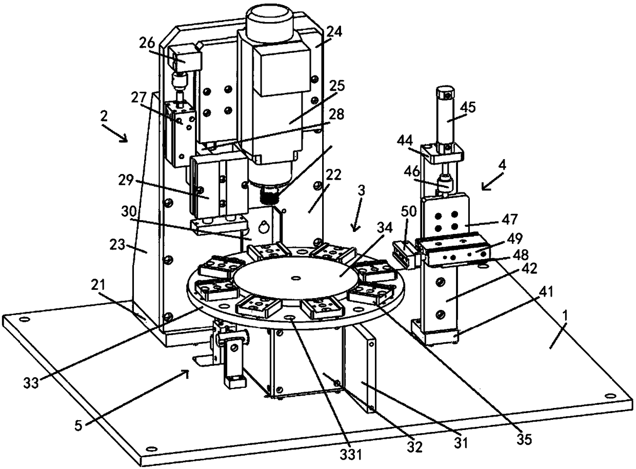
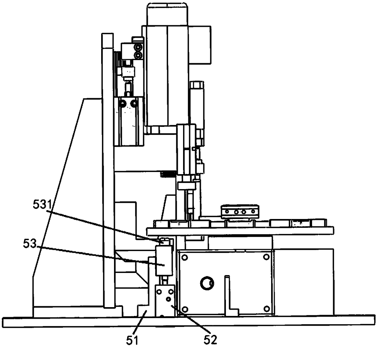
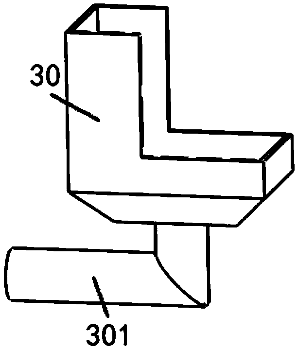
[0024] Such as Figure 1 to Figure 3 As shown, a kind of hardware button punching device that the present invention proposes comprises base plate 1; Described base plate 1 is fixed with punching mechanism 2, transplanting mechanism 3, cleaning mechanism 4 and positioning mechanism 5, and described transplanting mechanism 3 is set At the front end of the punching mechanism 2 , the cleaning mechanism 4 is arranged at the right end of the transplanting mechanism 3 , and the positioning mechanism 5 is located between the punching mechanism 2 and the transplanting mechanism 3 .

[0025] The punching mechanism 2 includes a base plate 21 placed flat on the base plate 1, and a mounting plate 22 perpendicular to the base plate 21 is fixe...


PUM


Abstract

The invention provides a hardware button punching device, comprising a bottom plate; The bottom plate is fixed with a perforating mechanism, a transplanting mechanism, a cleaning mechanism and a positioning mechanism, wherein the transplanting mechanism is arranged at the front end of the perforating mechanism, the cleaning mechanism is arranged at the right end of the transplanting mechanism, andthe positioning mechanism is positioned between the perforating mechanism and the transplanting mechanism; The perforating mechanism comprises a base plate which is flat on the base plate, and a mounting plate which is perpendicular to the base plate is fixed on the base plate through bolts and card slots; Between that rear side surface of the mount plate and the base plate, a reinforcing rib isfixed, and two right angle edge of the reinforcing rib are respectively bonded with the upper surface of the base plate and the rear side surface of the mounting plate; Two vertical sliding rails arefixed on the front surface of the mounting plate through bolts, and sliding blocks are slidably arranged on the sliding rails; A sliding plate is fixed on the slider by bolts, a rotating electric machine is inherently rotated on the slider by bolts, and an elastic chuck is arranged on the output shaft of the rotating electric machine and extends to the lower end.

Description

technical field [0001] The invention relates to the field of mechanical processing, in particular to a hardware button punching device. Background technique [0002] Buttons, in ancient Rome, the first buttons were used as decorations, and brooches were used to tie clothes; in the 13th century, the function of buttons was the same as today; at that time, people knew how to open buttonholes on clothes, which This method greatly improved the practical value of buttons; in the 16th century, buttons were popularized; with the rise of fast fashion, buttons have changed from the previous functional type to the current creative type; [0003] Nowadays, more and more hardware buttons are in demand, so that the defects of the existing button punching device are clarified; the position of the button blank on the carrier is uneven due to the factors in the rotation process or human factors of the existing button punching device , so as to produce defective products; although the exist...

Claims


Application Information

Patent Timeline
IPC IPC(8): B23Q11/00B23Q3/08
Inventor 姚力平
Owner JIASHAN COUNTY FEIHONG BUTTON FACTORY
Learn More