Gantry numerical control milling machine

A CNC milling machine and gantry technology, applied to milling machine equipment, milling machine equipment details, clamping, etc., can solve the problems of reducing production efficiency, increasing production cost, damage, etc., and achieve the goal of improving processing effect, reducing work intensity and improving production efficiency Effect

Active Publication Date: 2020-08-14
漳州东刚精密机械有限公司
View PDF7 Cites 2 Cited by
  • Summary
  • Abstract
  • Description
  • Claims
  • Application Information

AI Technical Summary

Problems solved by technology

[0005] Aiming at the deficiencies in the prior art, the object of the present invention is to provide a gantry CNC milling machine to solve the problem that when the milling cutter is processing the workpiece, the workpiece is directly placed on the milling machine without fixing the workpiece, causing the milling cutter to , the workpiece will be displaced, so that the milling cutter cannot process the workpiece uniformly, resulting in a low processing effect of the workpiece. It is necessary for the staff to adjust the position of the workpiece in real

Method used


Image

  • Gantry numerical control milling machine
  • Gantry numerical control milling machine
  • Gantry numerical control milling machine

Examples


Embodiment 1

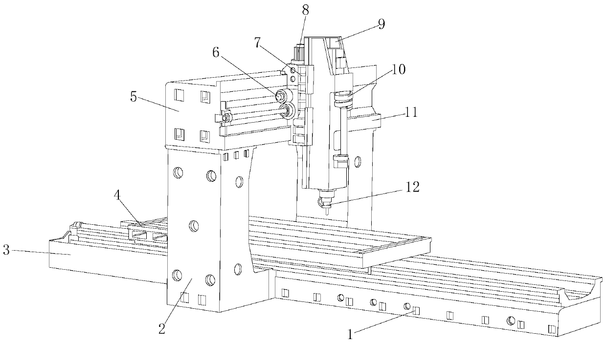
[0032] see figure 1 , the present invention provides a technical solution: a gantry numerical control milling machine, the structure of which includes a sliding sleeve block 1, a support frame 2, a milling machine table 3, a fixing device 4, a movable groove 5, a sliding plate 6, a fastening block 7, a micro motor 8. Milling head 9, anti-collision knife device 10, slide rail 11, milling cutter 12, the sliding sleeve block 1 is fixedly fitted on the left and right ends of the milling machine table 3, and the upper end of the milling machine table 3 is provided with a fixing device 4 , the milling machine table 3 is fixedly installed on the inner side of the support frame 2, the inner sides of the left and right ends of the support frame 2 are fitted with the milling machine table 3, the top of the support frame 2 is provided with a movable groove 5, and the movable groove 5 is provided with Sliding plate 6 and slide rail 11 are arranged, and described slide rail 11 is embedded...

Embodiment 2

[0039] see figure 1 , the present invention provides a technical solution: a gantry numerical control milling machine, the structure of which includes a sliding sleeve block 1, a support frame 2, a milling machine table 3, a fixing device 4, a movable groove 5, a sliding plate 6, a fastening block 7, a micro motor 8. Milling head 9, anti-collision knife device 10, slide rail 11, milling cutter 12, the sliding sleeve block 1 is fixedly fitted on the left and right ends of the milling machine table 3, and the upper end of the milling machine table 3 is provided with a fixing device 4 , the milling machine table 3 is fixedly installed on the inner side of the support frame 2, the inner sides of the left and right ends of the support frame 2 are fitted with the milling machine table 3, the top of the support frame 2 is provided with a movable groove 5, and the movable groove 5 is provided with Sliding plate 6 and slide rail 11 are arranged, and described slide rail 11 is embedded...


PUM


Abstract

The invention discloses a gantry numerical control milling machine. The gantry numerical control milling machine structurally comprises a sliding sleeve block, a supporting frame, a milling machine table, a fixing device, a movable groove, a sliding plate, a buckling block, a micro motor, a milling cutter head, an anti-collision cutter device, a sliding rail and a milling cutter. When the improvedgantry numerical control milling machine is used, the width of a limiting groove is adjusted through the cooperation of a protective spring and a traction rod, a to-be-machined workpiece is installedon a movable plate and fastened with the milling machine table through arc-shaped clamping blocks, so that the to-be-machined workpiece can be stably fixed to a machining position, air blowing treatment is conducted on gaps in the milling machine table through an air blowing head, and the cleanliness of the milling machine table is guaranteed. The milling cutter is installed in an anti-collisiontank, a lock catch and a clamping piece are matched to lock the milling cutter, a pull rod and a pull plate cooperates to pull the anti-collision tank, the milling cutter is pulled to a certain height, and the phenomenon that the milling cutter collides with the machined part is avoided. The milling cutter is protected using a buffer spring, the impact force generated when the pull rod pulls the milling cutter is reduced, and the production efficiency of the milling machine is improved.

Description

technical field [0001] The invention relates to the field of numerically controlled milling machines, in particular to a gantry numerically controlled milling machine. Background technique [0002] A milling machine is a machine tool that uses a milling cutter to mill a workpiece. It mainly refers to a machine tool that uses a milling cutter to process various surfaces on a workpiece. Usually, the rotation of the milling cutter is the main movement, and the movement of the workpiece and the milling cutter is the feed movement, which can be processed Planes and grooves can also process various curved surfaces and gears. The CNC milling machine is a machine tool that integrates a digital control system on an ordinary milling machine and can perform milling more accurately under the control of the program code. When the milling machine is working, it needs to be improved: [0003] 1. When the milling cutter is processing, the workpiece is directly placed on the milling machine...

Claims


Application Information

Patent Timeline
IPC IPC(8): B23C9/00B23Q3/06B23Q3/00B23Q11/00
CPCB23C9/00B23Q3/00B23Q3/06B23Q11/005
Inventor 王素莲
Owner 漳州东刚精密机械有限公司
Why Eureka
Try Eureka