
Multi-power extra-high-voltage vacuum arc extinguishing device

A technology of vacuum arc extinguishing and ultra-high voltage, applied in high-voltage air circuit breakers, high-voltage/high-current switches, circuits, etc., can solve the problems of polluting the inner wall of the insulating shell, inconvenient cleaning, etc., and achieve the effect of convenient operation and simple structure

Inactive Publication Date: 2019-07-05
兴化市天东软件科技有限公司
View PDF0 Cites 2 Cited by
  • Summary
  • Abstract
  • Description
  • Claims
  • Application Information

AI Technical Summary

Problems solved by technology

[0002] Vacuum arc extinguishing device, also known as vacuum switching tube, is the core component of medium and high voltage power switches. Its main function is to quickly extinguish the arc and suppress the current after the medium and high voltage circuits are cut off through the excellent insulation of the vacuum in the tube, so as to avoid accidents and accidents. It is mainly used in the power transmission and distribution control system of electric power. The vacuum arc extinguishing device is divided into arc extinguishing device for circuit breaker and arc extinguishing device for load switch. Disadvantages, the contact will generate a large amount of metal vapor and liquid droplets during the arcing process, which will cause pollution to the inner wall of the insulating shell, and it is inconvenient for the user to clean it. Therefore, in the process of use, it brings certain influence, for this reason, we propose a multi-power supply type UHV vacuum arc extinguishing device

Method used


Image

  • Multi-power extra-high-voltage vacuum arc extinguishing device
  • Multi-power extra-high-voltage vacuum arc extinguishing device
  • Multi-power extra-high-voltage vacuum arc extinguishing device

Examples


Embodiment Construction

[0017] In order to make the technical means, creative features, goals and effects achieved by the present invention easy to understand, the present invention will be further described below in conjunction with specific embodiments.

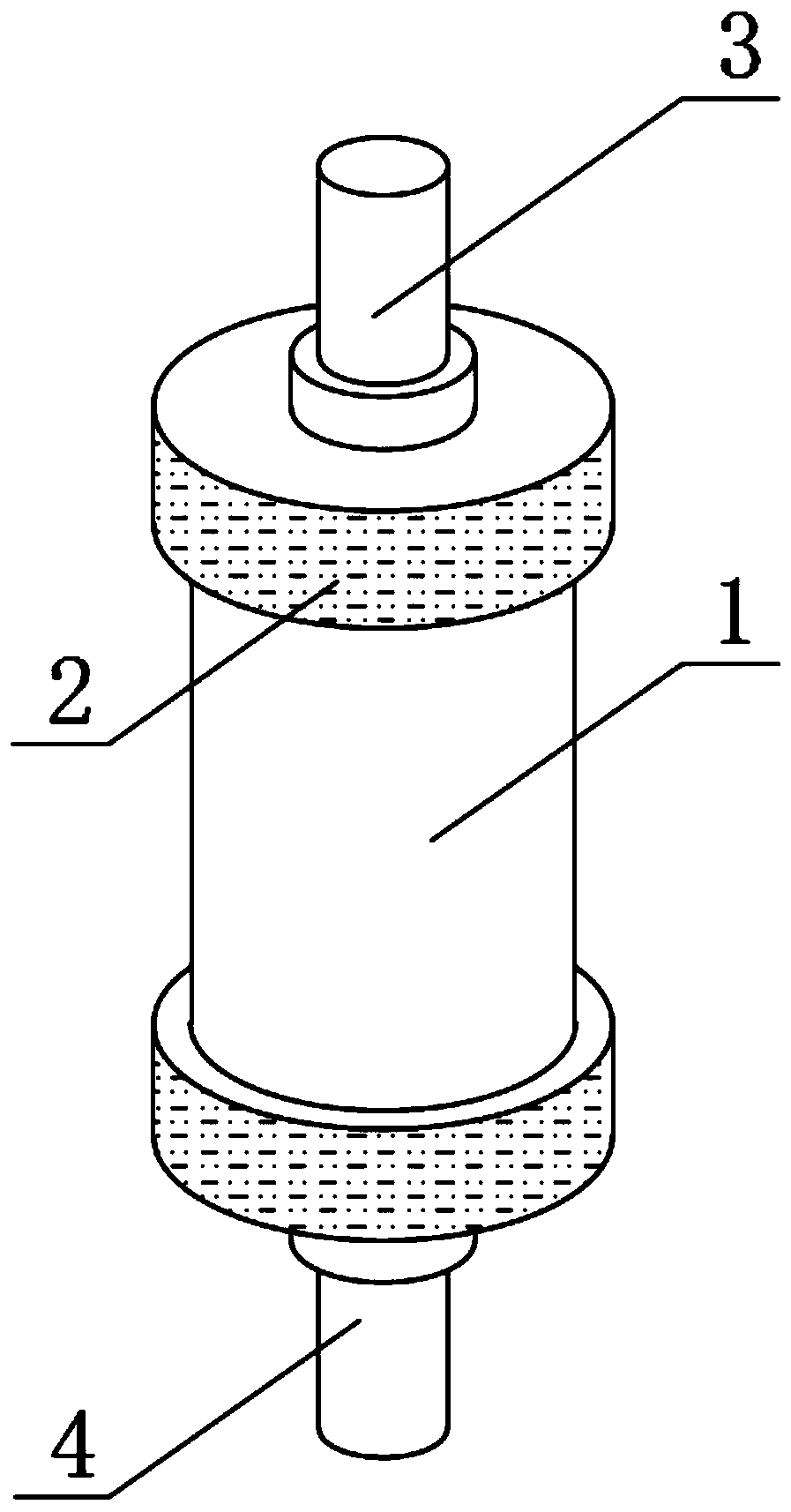
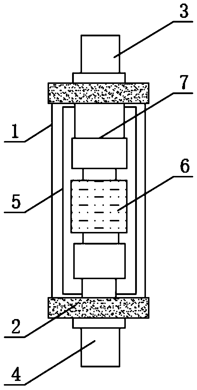
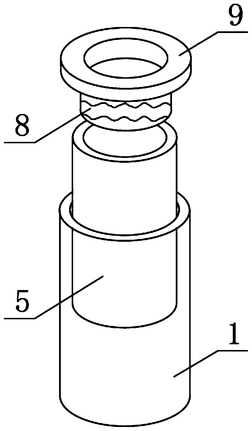
[0018] Such as Figure 1-4 As shown, a multiple power supply type UHV vacuum arc extinguishing device includes a main body shell 1 and an installation sleeve 2 sleeved on both ends of the outer surface of the main body shell 1, and a moving conductive rod 3 located on the outer surface of the upper end of the main body shell 1 and The static conductive rod 4 located on the outer surface of the bottom end of the main body shell 1, the inner wall of the main body shell 1 is provided with a shielding cylinder 5, the inside of the main body shell 1 is fixedly installed with a contact 6 and a bellows 7, and the bellows 7 is located on the contact 6 Above the shielding tube 5, a connecting sleeve 8 is provided, and the outer surface of the upper end of ...


PUM


Abstract

The invention discloses a multi-power extra-high-voltage vacuum arc extinguishing device. The device comprise a main body shell, mounting sleeve shells which are connected to the two ends of the outersurface of the main body shell in a sleeving mode, a movable conducting rod located on the outer surface of the upper end of the main body shell and a static conducting rod positioned on the outer surface of the bottom end of the main body shell; a shielding cylinder is arranged on the inner wall of the main body shell; a contact and a corrugated pipe are fixedly mounted in the main body shell; the corrugated pipe is located above the contact; a connecting sleeve is arranged above the shielding cylinder; a positioning ring is fixedly mounted on the outer surface of the upper end of the connecting sleeve; and a notch is formed in one side of the outer surface of the shielding cylinder. According to the multi-power extra-high-voltage vacuum arc extinguishing device, a user can convenientlytake out the shielding cylinder during use, so that the user can conveniently clean metal steam and liquid drops splashed on the shielding cylinder to keep the cleanness of the shielding cylinder; anda better application prospect is brought.

Description

technical field [0001] The invention relates to the field of arc extinguishing devices, in particular to a multi-power supply type UHV vacuum arc extinguishing device. Background technique [0002] Vacuum arc extinguishing device, also known as vacuum switching tube, is the core component of medium and high voltage power switches. Its main function is to quickly extinguish the arc and suppress the current after the medium and high voltage circuits are cut off through the excellent insulation of the vacuum in the tube, so as to avoid accidents and accidents. It is mainly used in the power transmission and distribution control system of electric power. The vacuum arc extinguishing device is divided into arc extinguishing device for circuit breaker and arc extinguishing device for load switch. Disadvantages, the contact will generate a large amount of metal vapor and liquid droplets during the arcing process, which will cause pollution to the inner wall of the insulating shell,...

Claims


Application Information

Patent Timeline
Patent Type & Authority Applications(China)
IPC IPC(8): H01H33/66H01H33/664
CPCH01H33/66261H01H33/664
Inventor 苏桂花
Owner 兴化市天东软件科技有限公司
Learn More