
A turning mechanism for corrugated paper printing

A technology of corrugated paper and paper turning, which is applied in the direction of turning over objects, pile separation, thin material processing, etc. It can solve the problems of poor fixing effect, achieve the effects of preventing scattering, speeding up efficiency, and saving costs

Inactive Publication Date: 2018-11-27
BEITANG JUNZHI PRINTING PAPER PROCESSING FACTORY
View PDF0 Cites 2 Cited by
  • Summary
  • Abstract
  • Description
  • Claims
  • Application Information

AI Technical Summary

Problems solved by technology

[0004] The object of the present invention is to provide a paper-turning mechanism for corrugated paper printing, to solve the problem of poor fixing effect in the above-mentioned background technology

Method used


Image

  • A turning mechanism for corrugated paper printing
  • A turning mechanism for corrugated paper printing
  • A turning mechanism for corrugated paper printing

Examples


Embodiment 1

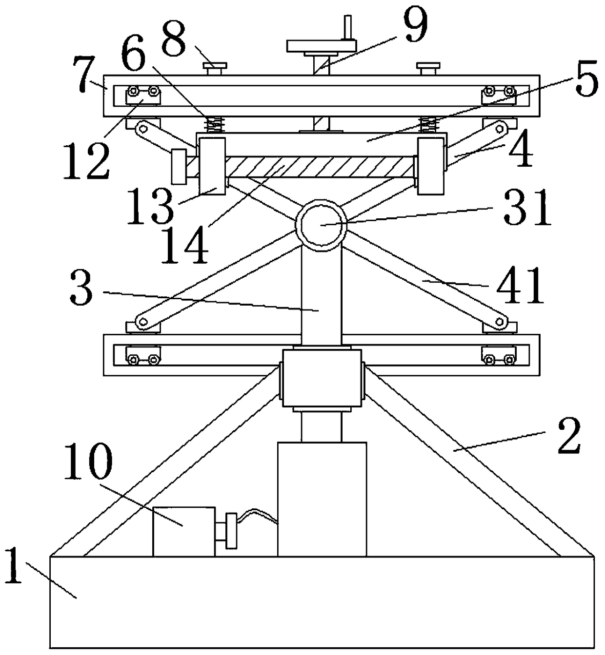
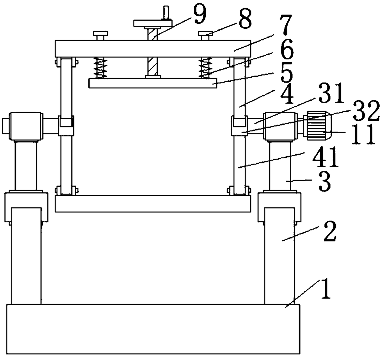
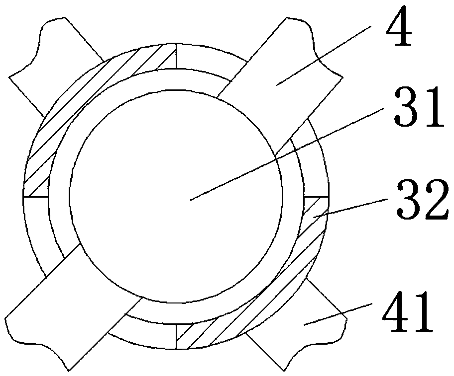
[0019] see Figure 1-3 , this embodiment provides a paper-turning mechanism for corrugated paper printing, including a base 1, a support frame 2 and a hydraulic lifting rod 3 are fixedly connected to the top of the base 1, and the top end of the hydraulic lifting rod 3 penetrates the supporting frame 2 and slides with the supporting frame 2 Connection, the inner side of the top of the hydraulic lifting rod 3 is connected with a rotating shaft 31, the outer side of the rotating shaft 31 away from the hydraulic lifting rod 3 is rotatably connected with a movable sleeve 32, and the outer side of the movable sleeve 32 is fixedly connected with a second support rod 41, the rotating shaft 31 is fixedly connected with the first support rod 4 at one end away from the hydraulic lifting rod 3, the first support rod 4 runs through the movable sleeve 32, the first support rod 4 and the second support rod 41 are in the same plane, the first support rod 4 and the second The outer sides of t...

Embodiment 2

[0022] see Figure 1-3 , on the basis of Embodiment 1, a further improvement is made: a chute is provided on the inside of the movable plate 7, and the slider 12 is connected to the inner wall of the chute by rolling on the rollers. The sliding on the inner side is smoother, which speeds up the working efficiency of the paper turning mechanism.

[0023] In the embodiment of the present invention, the inner sides of the fixed plate 5 and the movable plate 7 are provided with sponge pads, and placing the fixed plate 5 and the movable plate 7 too hard will cause damage to the corrugated paper, thereby better protecting the corrugated paper. Wherein, the threaded rod 14 and the threaded rod 9 are provided with a handle and a hand rocker respectively, which facilitates the adjustment of the distance between the movable plates 7 and the fixing of the corrugated paper, and accelerates the working efficiency of the paper turning mechanism. The hydraulic pump 10 passes through the infu...


PUM


Abstract

The invention discloses a turning mechanism for corrugated paper printing, including the base, A support frame and a hydraulic lifting rod are fixedly connecte at that top of the base, the top end ofthe hydraulic lifting rod penetrates the support frame and is slidably connected with the support frame, A rotating shaft is rotatably connected to the inner side of the top end of the hydraulic lifting lever, A movable sleeve is rotatably sleeved on the outer side of the rotating shaft away from one end of the hydraulic lifting rod, A second support rod is fixedly connected to the outer side of the movable sleeve, A first support rod is fixedly connected to one end of the rotating shaft away from the hydraulic lifting rod, the first support bar penetrates the movable sleeve, A sliding sleeveis slidably sleeved on the outer sides of the first support rod and the second support rod, and a screw rod is threadably connected between the two sliding sleeves. The invention solves the problem that the fixing effect of the traditional paper turning device on the corrugated paper is not good when the paper turning device is turned over, provides convenience for the subsequent printing work, saves the cost and accelerates the paper turning efficiency.

Description

technical field [0001] The invention relates to the technical field of corrugated paper printing processing equipment, in particular to a paper turning mechanism for corrugated paper printing. Background technique [0002] Corrugated paper is a plate made of liner paper and corrugated corrugated paper formed by processing corrugated sticks. It is generally divided into two types: single corrugated board and double corrugated board. According to the size of the corrugated board, it is divided into: A, B, C , E, F five types. The invention and application of corrugated paper has a history of more than 100 years. It has the advantages of low cost, light weight, easy processing, high strength, excellent printing adaptability, and convenient storage and transportation. More than 80% of corrugated paper can be recycled. Used as packaging for food or digital products, it is relatively environmentally friendly and widely used. [0003] Corrugated paper often needs to be turned ove...

Claims


Application Information

Patent Timeline
IPC IPC(8): B65H15/02
CPCB65H15/02B65H2701/1762
Inventor 余学润
Owner BEITANG JUNZHI PRINTING PAPER PROCESSING FACTORY
Learn More