Display panel, preparation method and display device with fingerprint recognition function

A fingerprint recognition and display panel technology, which is applied in the photoengraving process, recognition device, character and pattern recognition of the pattern surface, etc., can solve the problems of poor fingerprint recognition effect, etc., and achieve good fingerprint recognition effect, clear fingerprint image, and fingerprint recognition. Capture high-contrast effects

Active Publication Date: 2018-11-27
BOE TECH GRP CO LTD +1
View PDF5 Cites 7 Cited by
  • Summary
  • Abstract
  • Description
  • Claims
  • Application Information

AI Technical Summary

Problems solved by technology

[0006] The object of the present invention is to overcome the disadvantages of the poor fingerprint identification effect of the above-mentioned prior art, to provide a display panel with a fingerprint identification function with a better fingerprint identification effect, a preparation method of the display panel, and a display panel equipped with the fingerprint identification function. The display device of the display panel

Method used


Image

  • Display panel, preparation method and display device with fingerprint recognition function
  • Display panel, preparation method and display device with fingerprint recognition function
  • Display panel, preparation method and display device with fingerprint recognition function

Examples


Embodiment approach 1

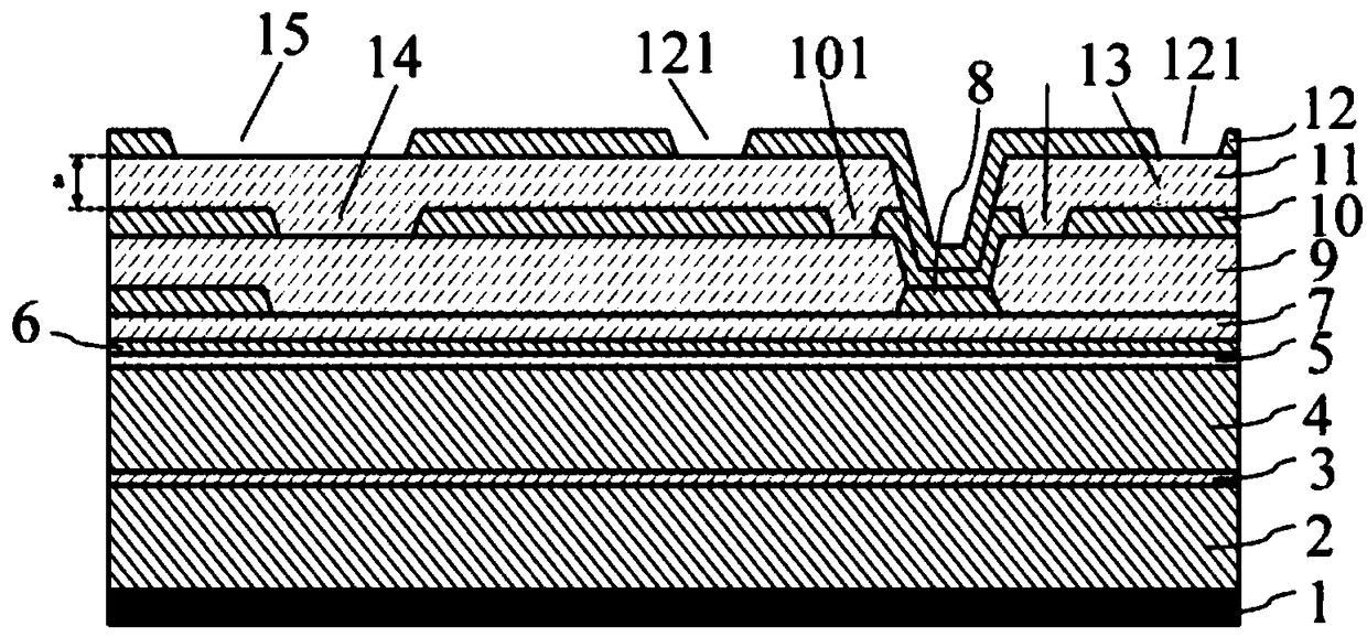
[0065] refer to Figure 5 Shown is a schematic structural view of an example embodiment of a display panel with fingerprint identification function of the present invention; the orthographic projection of the recessed area 111 on the metal light-shielding layer 10 partially overlaps with the orthographic projection of the first spacer area 101 on the metal light-shielding layer 10 , the position of the recessed area 111 is close to the first spacing area 101 . The orthographic projection of the recessed area 111 on the metal light-shielding layer 10 occupies a part of the first area and a part of the spacer area. Specifically, the side wall of the recessed area 111 away from the second spacing area 121 (or close to the connecting portion) is located between the two side walls of the first spacing area 101, and the side wall of the concave area 111 close to the second spacing area 121 (or away from the connecting portion) The sidewall of the part) is located between the sidewa...

Embodiment approach 2

[0072] refer to Figure 6 Shown is a schematic structural diagram of another exemplary embodiment of the display panel with fingerprint recognition function of the present invention; the difference between the second exemplary embodiment and the first exemplary embodiment is that: the orthographic projection of the recessed area 111 on the metal light-shielding layer 10 is different from the second The orthographic projections of the spacing area 121 on the metal light-shielding layer 10 partially overlap, that is, the position of the recessed area 111 is close to the second spacing area 121 . The orthographic projection of the recessed area 111 on the metal light-shielding layer 10 occupies the whole of the second area and a part of the spaced area. Moreover, the second spacing region 121 is not disposed on a plane, but is disposed in the recessed region 111 .

[0073] Specifically, the side wall of the recessed area 111 close to the first spacing area 101 (or close to the c...

Embodiment approach 3

[0079] The third exemplary embodiment is a further improvement on the second exemplary embodiment. refer to Figure 8 Shown is a schematic structural diagram of another exemplary embodiment of a display panel with a fingerprint identification function of the present invention; the difference between the third exemplary embodiment and the second exemplary embodiment is that the insulating layer 11 may include a first insulating layer 112 and a second insulating layer 113, the first insulating layer 112 is arranged on the metal light-shielding layer 10; the second insulating layer 113 is arranged between the first insulating layer 112 and the electrode layer 12, an opening is set on the second insulating layer 113, and the first insulating layer No recessed area is provided on 112 , and the opening is combined with the first insulating layer 112 to form a recessed area 111 .

[0080] Of course, the insulating layer 11 in the first exemplary embodiment may also be provided in th...


PUM

PropertyMeasurementUnit
Thicknessaaaaaaaaaa
Thicknessaaaaaaaaaa

Abstract

The invention relates to the field of display technology, and provides a display panel with a fingerprint recognition function. The display panel comprises a metal light shielding layer, an electrodelayer and an insulating layer; a first spacer region is disposed on the metal light shielding layer; a second spacer region is disposed on the electrode layer, wherein the second spacer region is offset from the first spacer region; the insulating layer is disposed between the metal light shielding layer and the electrode layer, and the insulating layer is provided with a recessed region; the orthographic projection of the recessed region on the metal light shielding layer is at least partially located between a first boundary and a second boundary; the first boundary is an orthographic projection of the sidewall of the first spacer region, away from the second spacer region, on the metal light shielding layer. The second boundary is an orthographic projection of the sidewall of the secondspacer region, away from the first spacer region, on the metal light shielding layer. The stray light refracted to the first spacer region through the insulating layer is reduced, so that the stray light incident on the photoelectric sensor is reduced, the fingerprint acquisition contrast is higher, the obtained fingerprint image is clearer, and the fingerprint recognition effect is better.

Description

technical field [0001] The invention relates to the field of display technology, in particular to a display panel with a fingerprint identification function, a method for preparing the display panel, and a display device equipped with the display panel with a fingerprint identification function. Background technique [0002] With the rapid development of full-screen mobile phones, the research on fingerprint recognition under the screen has received extensive attention. The existing technology uses the principle of pinhole imaging for fingerprint recognition under the screen, refer to figure 1 as well as figure 2 Shown is a schematic diagram of the structure of the integrated imaging pinhole array in the display panel in the prior art. In the figure, the square area is the imaging pinhole 14, and the annular area is the first interval area 101. The pinhole imaging principle is used in the display area 16 to realize The fingerprint is imaged on the photoelectric sensor, an...

Claims


Application Information

Patent Timeline
IPC IPC(8): G09F9/00G06K9/00G03F7/00
CPCG03F7/0005G09F9/00G06V40/1318H10K59/126H10K59/60H10K71/00
Inventor 颜俊魏玉龙董向丹李瀚刘庭良姚远
Owner BOE TECH GRP CO LTD
Why Eureka
Try Eureka