Limit device for electric furnace transformer body

A technology for electric furnace transformers and limit devices, which is applied in the directions of transformer/inductor housing, transformer/reactor installation/support/suspension, etc., which can solve problems such as uneven roads, insufficient transformer transportation and fixing, affecting safe transportation and hoisting of transformers, etc. , to reduce the impact of inertia and improve safety

Inactive Publication Date: 2018-11-27
合肥科达工业设备有限公司
View PDF0 Cites 1 Cited by
  • Summary
  • Abstract
  • Description
  • Claims
  • Application Information

AI Technical Summary

Problems solved by technology

This method will lead to sudden braking of the transformer during transportation, uneven roads, improper transportation of the transformer, and the effect of inertial force causing the body of the transformer to tilt back and forth and sway left and right, which seriously affects the safe transportation and hoisting of the transformer.

Method used


Image

  • Limit device for electric furnace transformer body

Examples


Embodiment Construction

[0012] The following will clearly and completely describe the technical solutions in the embodiments of the present invention with reference to the accompanying drawings in the embodiments of the present invention. Obviously, the described embodiments are only some, not all, embodiments of the present invention. Based on the embodiments of the present invention, all other embodiments obtained by persons of ordinary skill in the art without making creative efforts belong to the protection scope of the present invention.

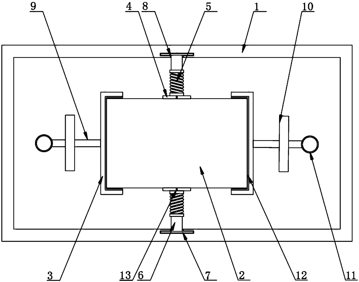
[0013] The present invention provides such figure 1 A body limit device for an electric furnace transformer as shown includes a box body 1, a transformer body 2 is arranged inside the box body 1, clamping plates 3 are arranged on both sides of the transformer body 2, and the front of the transformer body 2 The side and the rear side are all provided with an adsorption plate 4, the adsorption plate 4 is made of magnetic material, the surface of the adsorption p...


PUM


Abstract

The invention discloses a limit device for an electric furnace transformer body. The limit device comprises a box body, a transformer body is arranged in the box body, and clamping plates are arrangedon the two sides of the transformer body; attraction plates are arranged on the front and back side surfaces of the transformer body and are made from magnetic materials, springs are arranged on thesurfaces of the adsorption plates, and connecting rods are arranged at the ends of the springs; limit blocks are arranged at the ends of the connecting rods, a limit groove is formed in the inner wallof the box body, and the limit blocks are arranged in the limit groove. By arranging the springs, when the box body is subjected to the inertia, one of the front and back springs of the transformer body pulls the box body, the other spring pushes the box body, the inertial influence can be reduced, a buffer cushion made from rubber materials can have a buffering effect, the inertial influence isfurther reduced, and the improvement of the safety of transporting is facilitated.

Description

technical field [0001] The invention relates to the technical field of electric furnace accessories, in particular to a body limiting device for an electric furnace transformer. Background technique [0002] At present, in the field of electric furnace transformers, the positioning method of the transformer body is mainly by positioning at the bottom of the transformer oil tank or in the middle of the tank cover. The bottom of the transformer is welded into a rectangular frame with channel steel, and the feet of the body are positioned in the frame to limit its movement forward, backward, left, and right; while the middle part of the transformer box cover is pressed with pressing nails to prevent the body from moving up and down. . This method will cause the transformer to brake suddenly during transportation, the road is uneven, the transportation of the transformer is not fixed in place, and the action of inertial force will cause the body of the transformer to tilt back ...

Claims


Application Information

Patent Timeline
Patent Type & Authority Applications(China)
IPC IPC(8): H01F27/06H01F27/02
CPCH01F27/02H01F27/06
Inventor 李辉
Owner 合肥科达工业设备有限公司
Why Eureka
Try Eureka