Hydraulic controls and presses having such controls

A control device and technology for presses, applied in the field of presses, can solve problems such as unfavorable energy, and achieve the effects of improving efficiency, adjusting dynamic performance, and reducing cooling power

Active Publication Date: 2019-05-28
ROBERT BOSCH GMBH
View PDF9 Cites 0 Cited by
  • Summary
  • Abstract
  • Description
  • Claims
  • Application Information

AI Technical Summary

Problems solved by technology

[0006] However, it is still insufficient that the pressure medium quantity extruded from the working chamber is decompressed to the tank pressure only by means of a throttling device, which is disadvantageous in terms of energy

Method used


Image

  • Hydraulic controls and presses having such controls
  • Hydraulic controls and presses having such controls
  • Hydraulic controls and presses having such controls

Examples


Embodiment Construction

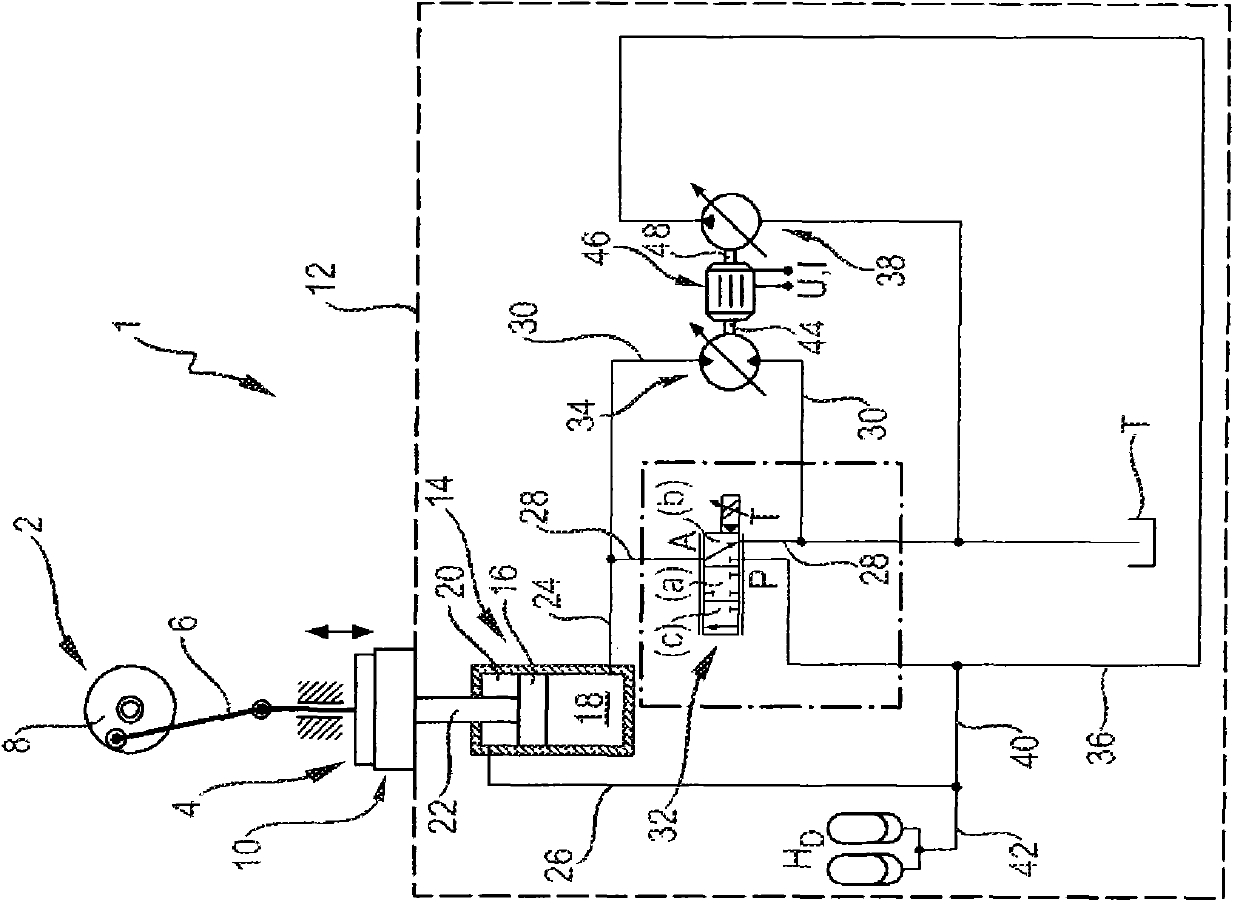
[0044] The press 1 shown in FIG. 1 has an upper die 4 driven by an eccentric drive mechanism 2 . It is connected to the drive mechanism 2 via the connecting rod 6. Press 1 is designed as a deep drawing machine. To apply force to the workpiece, the press 1 has a die holder 10 or a deep-drawing pad. During the stamping process, the machining force is applied to the workpiece by the upper die 4 via the counter-fixation of the deep-drawing pad 10 . In order to be able to adjust the force, the opposing fixing force of the die base 10 in the upper die 4 can be adjusted through the hydraulic control device 12 . The control device has a working cylinder 14 with a piston 16 , which delimits a working chamber or a pressure medium chamber 18 that acts against the punch 4 . The die holder 10 and thus the workpiece arranged between the die holder and the upper die 4 is supported on the piston 16 . The working cylinder 14 is designed as a double-acting differential cylinder and has a fu...


PUM


Abstract

The hydraulic control arrangement has a working cylinder (14) that is provided with a working chamber (18) into which a piston (16) passes, such that machinable workpiece is supported against an upper tool (4) that is connected with piston. An adjustable choke device (32) has a first pressure medium flow path (28) via which working chamber is connected with a pressure medium sink (T). A hydraulic machine (34) has a second pressure medium flow path (30) via which working chamber is connected to the pressure medium sink, for recuperation of the press work. An independent claim is included for press.

Description

technical field [0001] The invention relates to a hydraulic control device and a press with such a control device. Background technique [0002] Presses, in particular stamping machines, forming machines or deep-drawing machines, for the production of workpieces have upper and lower dies, via which pressure can be applied to the workpiece. For example, the upper mold is driven by an eccentric drive mechanism, and the upper mold usually performs a periodic lifting movement with a predetermined reciprocating rate and speed. The lower mold has a mold base, and if it is a deep drawing machine, it has a deep drawing pad, and the workpiece is laid on the mold base or deep drawing pad. In this case, the die holder or the deep-drawing cushion is supported by the working cylinder against the pressure exerted by the upper die. Among them, in order to ensure the quality of the workpiece, there are high force adjustment requirements for the supporting force of the working cylinder. T...

Claims


Application Information

Patent Timeline
Patent Type & Authority Patents(China)
IPC IPC(8): F15B11/08F15B1/02
CPCF15B21/14B30B15/16F15B2211/20515F15B2211/20546F15B2211/20569F15B2211/20576F15B2211/46F15B2211/625F15B2211/7058F15B2211/88
Inventor R·海登费尔德
Owner ROBERT BOSCH GMBH
Why Eureka
Try Eureka