Power grid control device

A technology for control devices and power grids, applied in the field of electric power, can solve problems such as threats to the safety of the power grid system, low mechanical performance, and single structure, and achieve the effects of easy use, strong safety, and fast on-off

Inactive Publication Date: 2018-11-27
WENLING JIUXIN IOT TECH CO LTD
View PDF0 Cites 0 Cited by
  • Summary
  • Abstract
  • Description
  • Claims
  • Application Information

AI Technical Summary

Problems solved by technology

[0002] In the power system, the most commonly used is the on-off switch. The existing switch has the disadvantages of single structure and low mechanical performance, and it has low safety in the actual use process, especially in the protection of large-scale power grid working circuits. Especially when a large amount of current passes through, a large amount of high heat is generated, which greatly threatens the safety of the power grid system. This device effectively solves this problem

Method used


Image

  • Power grid control device
  • Power grid control device
  • Power grid control device

Examples


Embodiment Construction

[0019] All features disclosed in this specification, or steps in all methods or processes disclosed, may be combined in any manner, except for mutually exclusive features and / or steps.

[0020] Any feature disclosed in this specification (including any appended claims, abstract and drawings), unless expressly stated otherwise, may be replaced by alternative features which are equivalent or serve a similar purpose. That is, unless expressly stated otherwise, each feature is one example only of a series of equivalent or similar features.

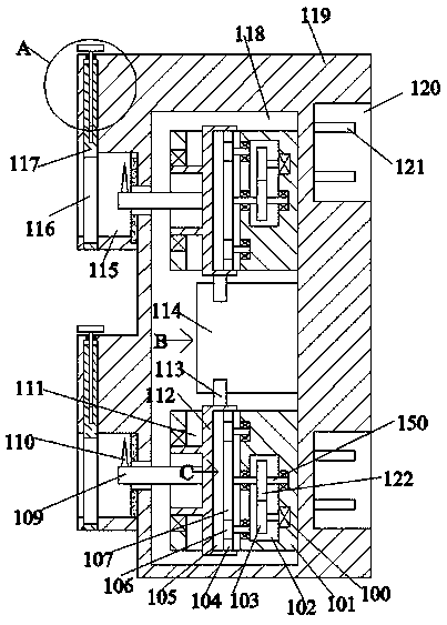
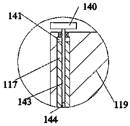
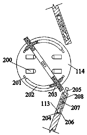
[0021] Such as Figure 1-4 As shown, a power grid control device of the present invention includes a box body 119, an inner cavity 118 is fixed inside the box body 119, and a vertically symmetrical side block 101 is fixed on the right end wall of the inner cavity 118. A drive chamber 102 is fixed in the block 101, a drive motor 100 is fixed in the right end wall of the drive cavity 102, an engagement gear 103 is fixed on the left end surface ...


PUM


Abstract

The invention discloses a power grid control device. The power grid control device comprises a box, wherein an inner cavity is fixedly formed in the box, vertically-symmetric side blocks are fixedly arranged on the right end wall of the inner cavity, transmission cavities are fixedly formed in the side blocks, driving motors are fixedly arranged in the right end walls of the transmission cavities,mesh gears are fixedly arranged on the left end surfaces of output shafts of the driving motors, mesh gears are arranged over the mesh gears in a meshed mode, through rotating shafts are fixedly arranged in the mesh gears, the through rotating shafts are connected with the right end walls of the transmission cavities in a rotating and matched mode, open cavities located in the side blocks are formed in the left sides of the transmission cavities, and the through rotating shafts penetrate through the transmission cavities in a rotating mode and extend into the open cavities. The power grid control device is simple in equipment structure and convenient to use, by adopting a mode of mechanical circuit system turn-on and turn-off control, fast and convenient turn-on and turn-off of two sets of complete circuits are achieved, and the power grid control device has high safety, so that the stability of an electric power system is greatly improved.

Description

technical field [0001] The invention relates to the field of electric power, in particular to a power grid control device. Background technique [0002] In the power system, the most commonly used is the on-off switch. The existing switch has the disadvantages of single structure and low mechanical performance, and it has low safety in the actual use process, especially in the protection of large-scale power grid working circuits. Especially when a large amount of current passes through, a large amount of high heat is generated, which greatly threatens the safety of the power grid system. This device effectively solves this problem. Contents of the invention [0003] The object of the present invention is to provide a grid control device capable of overcoming the above-mentioned defects in the prior art. [0004] According to the present invention, a power grid control device of the equipment of the present invention includes a box body, an inner cavity is fixed in the bo...

Claims


Application Information

Patent Timeline
Patent Type & Authority Applications(China)
IPC IPC(8): H01H3/26H01H3/28H01H3/32
CPCH01H3/26H01H3/28H01H3/32
Inventor 吴娜
Owner WENLING JIUXIN IOT TECH CO LTD
Why Eureka
Try Eureka