Treatment table with rotary opening function by aid of different rotary shafts

A technology for rotary opening and treatment table, applied in the field of treatment table, can solve the problems of reducing the working efficiency of medical staff, increasing the labor intensity of medical staff, inconvenient to place on the treatment table, etc., and achieving the effect of convenience for medical staff and improving work efficiency

Inactive Publication Date: 2018-11-30
东莞市金越信息科技有限公司
View PDF5 Cites 0 Cited by
  • Summary
  • Abstract
  • Description
  • Claims
  • Application Information

AI Technical Summary

Problems solved by technology

[0003] When the medical staff needs to take things out of the drawer, the medical staff needs to pull out the drawer from the drawer slot, and the drawn drawer keeps the medical staff away from the treatment table, so it is inconvenient for the medical staff to place the things taken out of the drawer on the treatment table , especially when the medical staff need to access the things inside the drawer
[0004] When the amount of treatment is large, many people are often required to add medicine around the treatment table. The traditional pull-out drawer is extremely inconvenient for many people to take medicine at the same time, and they often need to avoid each other, which increases the labor intensity of medical staff and reduces the cost of medical staff. work efficiency

Method used


Image

  • Treatment table with rotary opening function by aid of different rotary shafts
  • Treatment table with rotary opening function by aid of different rotary shafts
  • Treatment table with rotary opening function by aid of different rotary shafts

Examples


Embodiment Construction

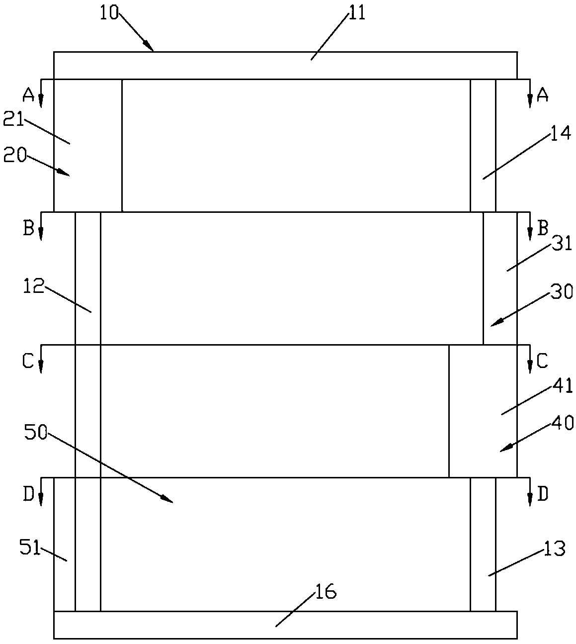
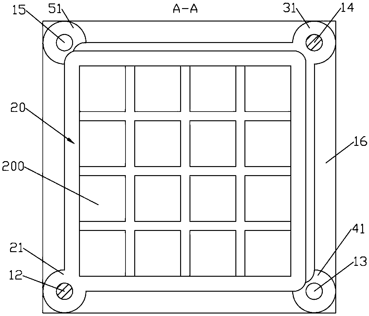
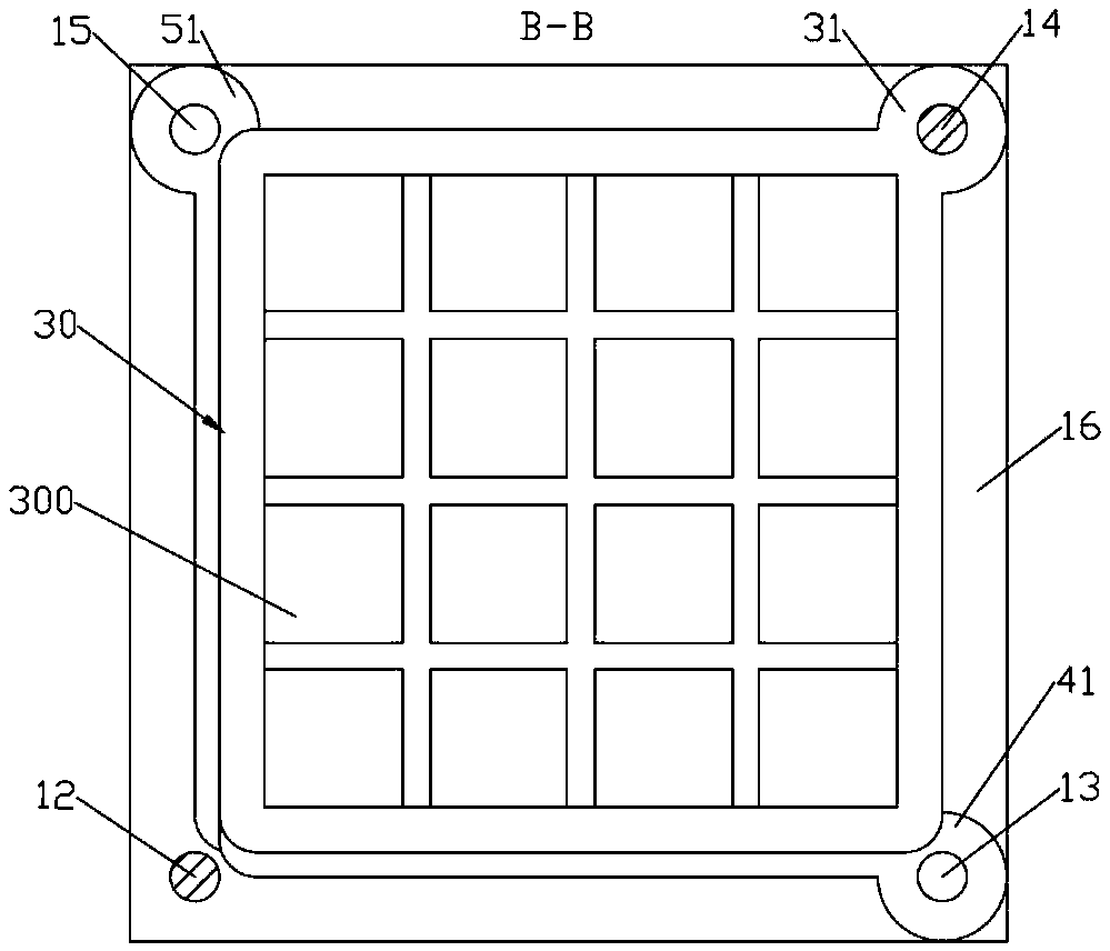
[0021] Such as Figure 1 to Figure 8 As shown, a treatment table that can be rotated and opened with different rotation axes includes a frame 10, a first drawer 20, a second drawer 30, a third drawer 40 and a fourth drawer 50; the frame 10 includes an upper support plate 11, a lower support plate Plate 16, left front support bar 12, right front support bar 13, right rear support bar 14 and left rear support bar 15; Upper support plate 11 and lower support plate 16 are square plates; Left front support bar 12, right front support bar 13, right back The support bar 14 and the left rear support bar 15 are cylinders and the circumference is evenly distributed; the left front support bar 12 is vertically arranged between the upper support plate 11 and the lower support plate 16; Right front corner; Right rear support rod 14 is arranged on the right rear corner of the lower end face of upper support plate 11; Left rear support rod 15 is arranged on the left rear corner of the upper ...


PUM


Abstract

The invention discloses a treatment table with a rotary opening function by the aid of different rotary shafts. The treatment table comprises a framework, a first drawer, a second rawer, a third drawer and a fourth drawer. The framework comprises an upper support plate, a lower support plate, a left front support rod, a right front support rod, a right rear support rod and a left rear support rod;the upper support plate and the lower support plate are square plates; the left front support rod is vertically arranged between the upper support plate and the lower support plate; the right front support rod is arranged at the right front corner of the upper end surface of the lower support plate; the right rear support rod is arranged at the right rear corner of the lower end surface of the upper support plate; the left rear support rod is arranged at the left rear corner of the upper end surface of the lower support plate. The treatment table has the advantages that the first drawer, thesecond drawer, the third drawer and the fourth drawer can be rotationally opened around the different rotary shafts and are positioned in different directions after being opened, accordingly, the requirements of medical staffs on simultaneously fetching articles from the different drawers can be met, the treatment table can bring convenience for the medical staffs, and the work efficiency of the medical staffs can be improved.

Description

technical field [0001] The invention relates to medical equipment, in particular to a treatment table which can be rotated and opened with different rotation axes. Background technique [0002] The treatment table is one of the necessary items in the treatment room of the hospital. At present, the position of the hospital treatment table is fixed, and most of them are cabinet-type. Fixed position. [0003] When the medical staff needs to take things out of the drawer, the medical staff needs to pull out the drawer from the drawer slot, and the drawn drawer keeps the medical staff away from the treatment table, so it is inconvenient for the medical staff to place the things taken out of the drawer on the treatment table , especially when the medical personnel need to access the things inside the drawer. [0004] When the amount of treatment is large, many people are often required to add medicine around the treatment table. The traditional pull-out drawer is extremely incon...

Claims


Application Information

Patent Timeline
IPC IPC(8): A61B50/15A61B50/18A61G12/00
CPCA61B50/15A61B50/18A61B2050/185A61G12/00
Inventor 徐亚维
Owner 东莞市金越信息科技有限公司
Why Eureka
Try Eureka