
Environment-friendly mechanical seal cavity structure for pump and method for controlling temperature of cooling medium

A mechanical seal and environmentally friendly technology, applied in mechanical equipment, components of pumping devices for elastic fluids, pumps, etc., can solve the problems of time-consuming and labor-intensive, complicated replacement process, and inability to intuitively grasp the cooling and lubricating medium in real time.

Active Publication Date: 2019-08-20
ZHEJIANG LBX PUMP IND
View PDF6 Cites 0 Cited by
  • Summary
  • Abstract
  • Description
  • Claims
  • Application Information

AI Technical Summary

Problems solved by technology

Before the replacement, the motor unit of the pump body needs to be removed to replace the cooling and lubricating medium. At the same time, the replacement process is also extremely complicated
Therefore, in the prior art, the quality of the cooling and lubricating medium cannot be grasped intuitively in real time; and there are too many procedures in the replacement process, cumbersome operations, time-consuming and labor-intensive operations, difficult maintenance, and high unknown risks, which directly affect the effective use of the pump body

Method used


Image

  • Environment-friendly mechanical seal cavity structure for pump and method for controlling temperature of cooling medium
  • Environment-friendly mechanical seal cavity structure for pump and method for controlling temperature of cooling medium
  • Environment-friendly mechanical seal cavity structure for pump and method for controlling temperature of cooling medium

Examples


Embodiment 1

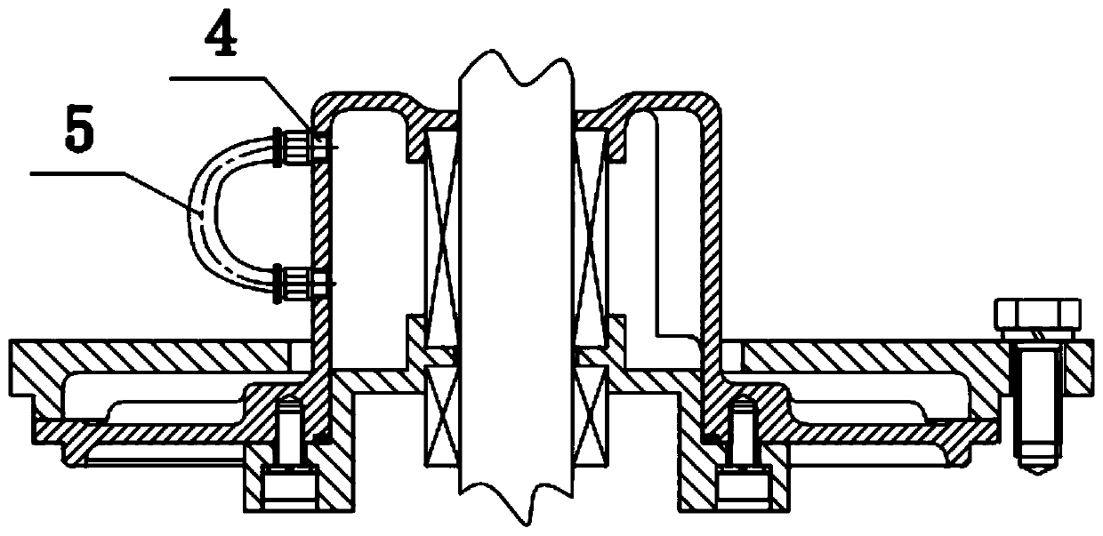
[0054] as attached figure 1 As shown, there is an environment-friendly mechanical seal cavity structure for a pump, and two liquid injection holes 4 communicating with the outside are arranged on the side wall of the seal cavity structure along the axial direction of the pump shaft. The two liquid injection holes 4 communicate through an observation device 5 located outside the sealed chamber structure. Wherein, one liquid injection hole 4 is arranged close to the motor of the pump body, and the other liquid injection hole 4 is arranged close to the impeller. The two injection holes 4 can be coaxially opened up and down, and can also be staggered up and down. For the convenience of connection and observation, in this solution, the two liquid injection holes 4 are coaxially arranged up and down. Managers can intuitively and real-time grasp the state of the cooling and lubricating medium in the sealing cavity through the observation device 5, for example, they can judge whethe...

Embodiment 2

[0057] Such as figure 1 As shown, the observation device 5 includes a transparent rubber tube, and the transparent rubber tube can be a transparent silicone tube with high transparency and moderate hardness. The two ports of the transparent rubber tube are respectively connected with the two liquid injection holes 4, so that the transparent rubber tube communicates with the sealing cavity, and at the same time, the cooling lubricating medium enters the transparent rubber tube. By directly observing the cooling and lubricating medium in the transparent hose, you can easily grasp the real-time status of the cooling and lubricating medium, and then judge whether the pump body is working abnormally.

[0058] In this technical solution, the transparent rubber tube is connected to the liquid injection hole 4 on the sealed cavity structure by quick connection, so as to realize the quick docking and disengagement of the transparent rubber tube and the sealed cavity structure.

[0059...

Embodiment 3

[0067] When the pipeline pump transports hot water and other high-temperature flow media, and the cooling and lubricating medium in the sealed cavity needs to be circulated, preferably, the observation device 5 is also connected with a cooling and lubricating medium storage device (not shown in the figure) located outside the sealed cavity structure. show). A detachable transparent rubber hose can be selected, for example, the transparent rubber hose is in two sections, which are connected as a whole by threads. If an external cooling and lubricating medium storage device is required, the transparent rubber tube can be separated along the middle, and then the two free ends are respectively connected to the cooling and lubricating medium storage device. At this time, the cooling and lubricating medium storage device communicates with the sealing cavity through the transparent rubber tube. Since the liquid injection hole 4 is set high and low, the temperature difference of the ...


PUM


Abstract

The invention provides an environment-friendly mechanical sealing cavity structure for a pump and a method for controlling the temperature of a cooling medium. Two liquid injection holes communicatingwith the outside are formed in the side wall of the sealing cavity structure in the axial direction of a pump shaft, and the two liquid injection holes communicate with each other through an observation device located outside the sealing cavity structure. The structure and the method have the beneficial effects that the two independent liquid injection holes are formed in the side surface of a sealing cavity, moreover, liquid injection holes communicate with each other through a transparent guide pipe, the cooling lubricating medium exists in the transparent guide pipe, management personnel can visually see the real-time state of the cooling lubricating medium in the transparent guide pipe, and then the real-time condition of the cooling lubricating medium in the sealing cavity is mastered; and when the cooling lubricating medium is replaced, the transparent rubber pipe is pulled out directly and rapidly and is connected to a cooling lubricating medium external storage device so thaton the premise that a pump body motor set is not detached, and the cooling and lubricating medium in the sealing cavity can be quickly replaced by a self-circulation mode.

Description

technical field [0001] The invention relates to the technical field of pump body sealing devices, in particular to an environment-friendly mechanical seal chamber structure for a pump and a method for controlling the temperature of a cooling medium. Background technique [0002] The pipeline pump is a kind of single-suction single-stage or multi-stage centrifugal pump. It is a vertical structure. Its inlet and outlet are on the same straight line, and the diameter of the inlet and outlet is the same. It is like a section of pipeline and can be installed in any position of the pipeline. [0003] The mechanical seal device in the pipeline pump structure is installed on the pump shaft and located in the mechanical seal chamber structure of the pipeline pump. Wherein, the mechanical seal cavity structure includes a mechanical seal cover plate and a pump cover respectively sleeved on the pump shaft, and a cavity enclosed by the mechanical seal cover plate and the pump cover. Dur...

Claims


Application Information

Patent Timeline
Patent Type & Authority Patents(China)
IPC IPC(8): F04D29/58F04D29/06F04D29/10
Inventor 王护桥师延盛叶腾翔
Owner ZHEJIANG LBX PUMP IND
Learn More