Concrete pouring formwork bracket

A concrete and formwork technology, applied in the field of concrete pouring, can solve the problems of exceeding the tensile strength of the spring, affecting the service life, insufficient strength, etc., and achieving the effects of avoiding the troweling process, facilitating assembly, and convenient operation.

Inactive Publication Date: 2018-12-07
CHONGQING HUASHUO CONSTR
View PDF5 Cites 2 Cited by
  • Summary
  • Abstract
  • Description
  • Claims
  • Application Information

AI Technical Summary

Problems solved by technology

Although this patent solves the problem of long service life of the existing formwork and cushion strips, it is fixed on the crossbar by a hook when connecting, so that a lot of force is used every time the crossbar needs to be pulled, and the operation is troublesome
Moreover, the hooks in the application documents are jagged, that is, the distance each time the spring is stretched can only be an integral multiple of the length of the sawtooth, or the fixing strength is not enough, or it exceeds the tensile strength of the spring, which affects the service life

Method used


Image

  • Concrete pouring formwork bracket
  • Concrete pouring formwork bracket

Examples


Embodiment Construction

[0013] The present invention will be further described in detail below through specific implementations:

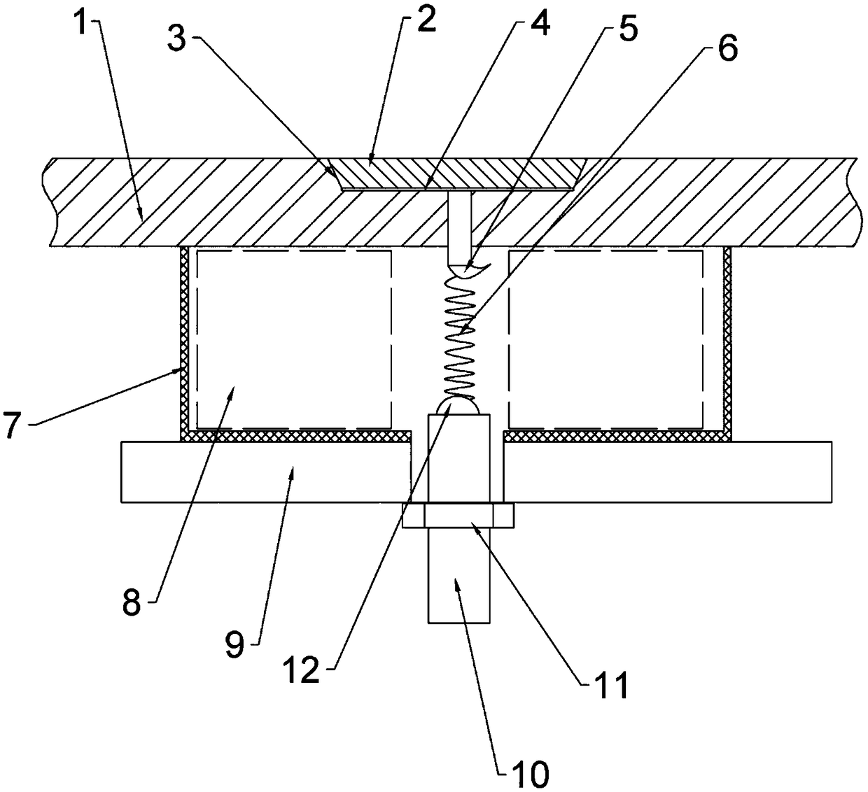
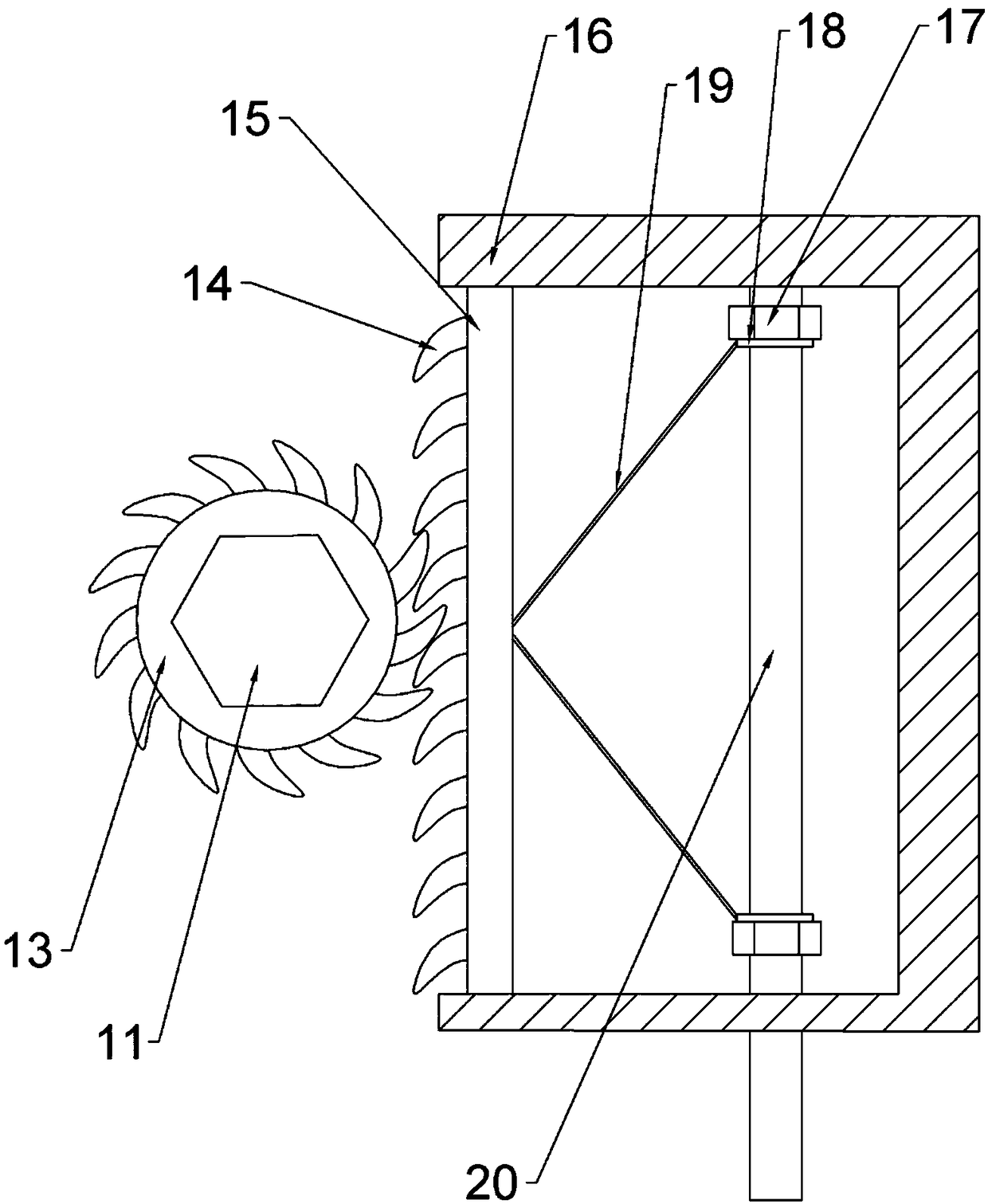
[0014] The reference signs in the drawings of the specification include: template 1, connecting piece 2, sinking groove 3, rubber pad 4, first hook 5, spring 6, clamping piece 7, cushion strip 8, bracket 9, screw 10, nut 11. The second hook 12, the ratchet gear 13, the ratchet teeth 14, the connecting plate 15, the fixing plate 16, the fixing nut 17, the ring 18, the connecting rod 19, and the two-way screw 20.

[0015] The embodiment is basically as attached figure 1 Shown: concrete pouring formwork support, including formwork 1, cushion strip 8, connecting piece 2, spring 6, fixed part and bracket 9. The connecting piece 2 is a connecting piece 2 made of metal material, and the connecting piece 2 made of metal material has better strength and better connection effect. The support 9 is built into a frame shape, the top of the support 9 is provided with a plurality of mat str...


PUM


Abstract

The invention belongs to the technical field of concrete pouring, and particularly discloses a concrete pouring formwork bracket. The concrete pouring formwork bracket comprises a plurality of formworks, a plurality of stepping bars, a connecting piece, a spring, a fixing portion and brackets. The brackets are built to frame shapes, the multiple stepping bars are arranged at the tops of the brackets, the multiple formworks are arranged on the top surfaces of the stepping bars, and the multiple formworks are form a plane in a splicing mode. A sinking groove is formed in the spliced edges of theformworks, a through hole is formed in the edge of the sinking groove, and the connecting piece is adaptive to the shape of the sinking groove and can be placed in the sinking groove. A first hook isarranged on the bottom of the connecting piece, the first hook penetrate through the through hole, and clamping and connecting pieces are arranged on the lower portions of the stepping bars. The upper end of the spring is connected with the hook in a hanging mode, the fixing portion is connected with the lower end of the spring, the fixing portion is fixed to the brackets and comprises a nut anda threaded rod, a second hook connected with the spring is arranged at one end of the threaded rod, the nut is matched with the threaded rod in a threaded mode, and the nut abuts against the lower endsurfaces of the brackets. The concrete pouring formwork bracket can improve the efficiency during assembling and disassembling, operation is convenient and the service life is prolonged.

Description

Technical field [0001] The invention relates to the technical field of concrete pouring, in particular to a formwork support for concrete pouring. Background technique [0002] At present, my country has entered a period of rapid development of the national economy, and the scale of infrastructure construction has been unprecedentedly expanded. It has put forward higher requirements on the technology and management of building construction. In civil construction, scaffolding and formwork brackets are widely used because they are very convenient and flexible to erect and dismantle. . In order to ensure the stability of the structure and avoid collapse accidents during the pouring process of the traditional concrete pouring formwork support, when building the formwork support, the formwork and the cushion are connected by long nails, which is inefficient in installation, time-consuming, laborious, and difficult. Ensure the flatness of the spliced ​​formwork, resulting in uneven con...

Claims


Application Information

Patent Timeline
Patent Type & Authority Applications(China)
IPC IPC(8): E04G17/00
CPCE04G17/001
Inventor 袁昌勇车军伟王飞程帅
Owner CHONGQING HUASHUO CONSTR
Why Eureka
Try Eureka