Valve axial force testing device and testing method thereof

A testing device, valve device technology, applied in the direction of measuring device, measuring force, instrument, etc., can solve the problems of waste, lack of actual data of valve axial force, restricting technological progress and quality improvement, etc.

Pending Publication Date: 2018-12-07
HUANGSHAN LIANGYE VALVE
View PDF0 Cites 0 Cited by
  • Summary
  • Abstract
  • Description
  • Claims
  • Application Information

AI Technical Summary

Problems solved by technology

[0003] In the process of realizing the present invention, the inventor found that the prior art has at least the following problems: According to the domestic industry survey and scientific and technological novelty search, it is still a blank field in China for the test and test of the size of the axial force and stability. There is no means and equipment for detecting the axial force of the valve
It can't even reflect the corresponding relationship between axial force and opening (stroke) position. Therefore, it brings blindness to the design, manufacturing process and use of the valve. There are also frequent problems in the selection and matching of equipment, often either because of excess selection, which causes waste, or because of insufficient selection of axial force, which makes it impossible to use normally, which seriously restricts the technological progress and quality improvement in this field.

Method used


Image

  • Valve axial force testing device and testing method thereof
  • Valve axial force testing device and testing method thereof
  • Valve axial force testing device and testing method thereof

Examples


Embodiment 1

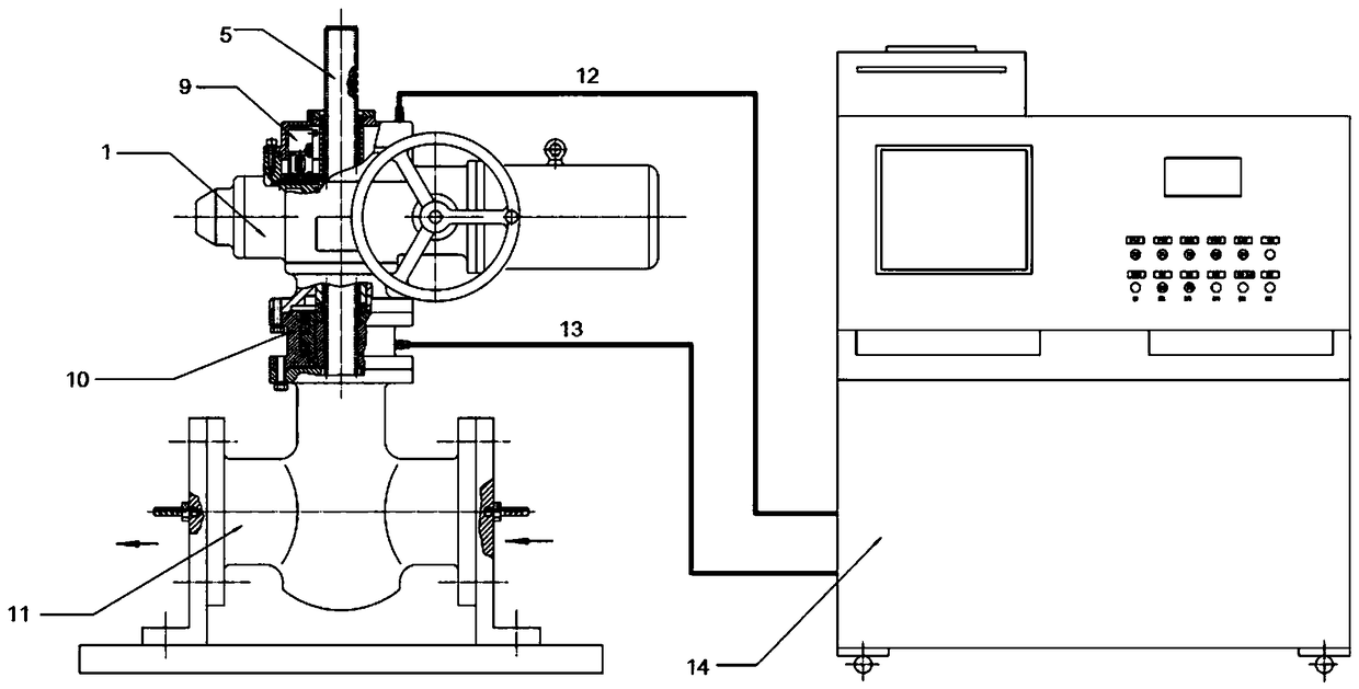
[0043] see Figure 1-5 , a valve axial force testing device, having:

[0044] The valve to be tested;

[0045] A driving device, the output shaft of the driving device is connected to the valve stem of the valve to be tested;

[0046] A connector, the first end of which is connected to the driving device, and the second end is connected to the valve stem;

[0047] An axial force sensor is arranged on the joint;

[0048] The encoder is arranged in the driving device and can measure the rotation angle of the output shaft of the driving device;

[0049] Control cabinet;

[0050] Axial force sensor signal cable, connecting the axial force sensor and the control cabinet;

[0051] The drive unit cable connects the drive unit to the control cabinet, and the drive unit cable is also connected to the encoder.

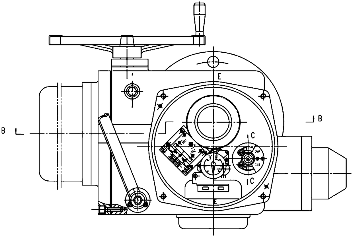
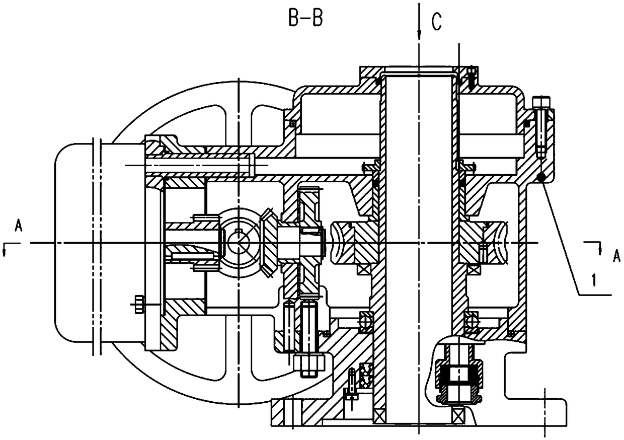
[0052] The driving device is a valve device; the valve device includes:

[0053] box;

[0054] The intermediate shaft is rotatably installed in the box;

[0055] The wo...

Embodiment 2

[0075] A test method of the valve axial force testing device described above, the upper bolt of the axial force sensor is connected to the driving device, the lower bolt is connected to the valve to be tested, and the encoder is arranged in the electric box cover of the driving device. When measuring, the valve to be tested must be in the pressure test condition, that is, there is a load;

[0076] The driving device runs, drives the encoder to rotate, outputs pulses to the control cabinet for counting, and the data enters the control cabinet for recording and processing;

[0077] The output shaft rotates to drive the valve stem up and down, causing axial force to appear at both ends of the axial force sensor, and the resistance value of the strain gauge in it changes, which is converted into analog data and converted into digital signal by A / D to enter the control cabinet;

[0078] After all the data signals are processed by the control cabinet, they are output through the bre...


PUM


Abstract

The invention discloses a valve axial force testing device and a testing method thereof. The valve axial force testing device includes a valve to be tested; a driving device, wherein an output shaft of the driving device is connected with a valve rod of the valve to be tested; a joint, wherein a first end of the joint is connected with the driving device, and a second end of the joint is connectedwith the valve rod; an axial force sensor disposed on the joint; an encoder which is disposed in the driving device and can measure the rotation angle of the output shaft of the driving device; a control cabinet; an axial force sensor signal cable for connecting the axial force sensor and the control cabinet; and a driving device cable for connecting the driving device and the control cabinet, wherein the driving device cable are also connected to the encoder. The continuous value of a corresponding relation between the opening and closing axial force and the opening degree (stroke) can be obtained during the actual measurement of the valve.

Description

technical field [0001] The invention belongs to the technical field of valve detection, and in particular relates to a valve axial force test device and a test method thereof. Background technique [0002] For the multi-turn straight-stroke valves widely used in the industrial field, such as gate valves and globe valves, in order to realize opening and closing, torque must be applied to the valve stem and nut to convert it into an upward or downward axial force. The applied torque can be manually , can also be electric or pneumatic. To make the valve tightly closed, sufficient sealing specific pressure must be generated on the sealing surface, which is mainly given by the axial force (some may include medium pressure). [0003] In the process of realizing the present invention, the inventor found that the prior art has at least the following problems: According to the domestic industry survey and scientific and technological novelty search, it is still a blank field in Chin...

Claims


Application Information

Patent Timeline
Patent Type & Authority Applications(China)
IPC IPC(8): G01L1/22
CPCG01L1/22
Inventor 项美根项晓明
Owner HUANGSHAN LIANGYE VALVE
Why Eureka
Try Eureka