Check patentability & draft patents in minutes with Patsnap Eureka AI!

Computer interface device

An interface device and computer technology, which is applied in the direction of computer peripheral equipment connectors, parts of connection devices, coupling devices, etc., can solve problems such as small diameter bolts, difficulty in manually rotating bolts with a screwdriver, troubles in computer assembly and maintenance, etc., and achieve practical Strong, simple structure effect

Inactive Publication Date: 2018-12-07
重庆青年职业技术学院
View PDF8 Cites 0 Cited by
  • Summary
  • Abstract
  • Description
  • Claims
  • Application Information

AI Technical Summary

Problems solved by technology

[0003] Most people are able to vacate a large desktop space, and all place the computer mainframe at the corner of the bottom of the desktop. The length of the signal cable is too short and can only be operated under the table, which will cause troubles in computer assembly and maintenance
[0004] In view of the above problems, the existing p

Method used


Image

  • Computer interface device
  • Computer interface device
  • Computer interface device

Examples


Embodiment 1

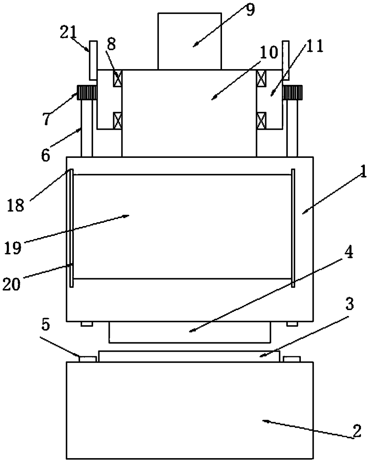
[0021] see Figure 1~3 , in an embodiment of the present invention, a computer interface device includes a No. 1 connecting body 1 and a No. 2 connecting body 2. The lower end of the No. 1 body 1 is provided with a No. 1 connecting port 4, and the upper end of the No. 2 body 2 is provided with a The No. 2 interface 3 matched with the interface 14, the No. 1 interface 14 and the No. 2 interface 3 are all rectangular tubes, the outer surface of the No. 1 interface 14 matches the inner wall of the No. 2 interface 3, and the outer side of the No. 1 interface 14 is also provided with a pretension layer 4. The pretension layer 4 is a rubber layer, and the setting of the pretension layer 4 makes the first interface 14 and the second interface 3 tightly connected;

[0022] The upper end of No. 1 connecting body 1 is provided with a fixed sleeve 10, and the upper end of the fixed sleeve 10 is provided with a connecting column 9. The outer side of the fixed sleeve 10 is rotated and prov...

Embodiment 2

[0024] The difference from Embodiment 1 is that the No. 1 connecting body 1 is also provided with a dust-proof mechanism, and the dust-shielding mechanism includes a shielding plate 19, and two sliding bars are arranged on the No. 1 connecting body 1 at the left and right ends of the shielding plate 19. 18. The sliding bar 18 is provided with a slide groove matched with the shielding plate 19, and the upper surface of the shielding plate 19 is provided with an anti-slip layer. After connecting the first connector 1 and the second connector 2, the shielding plate 19 Slide down to cover the connection between the No. 2 connection port 3 and the No. 1 connection port 14, thereby improving the dustproof effect of the connection device.


PUM


Abstract

The invention discloses a computer interface device, which comprises a connecting body I and a connecting body II, wherein the lower end of the body I is provided with a connecting port I, the upper end of the body II is provided with a connecting port II matched with the connecting port I, both the connecting port I and the connecting port II are rectangular tubes, and the outer side surface of the connecting port I is matched with the inner wall of the connecting port II. The computer interface device is simple and reasonable in structure, the outer side of a fixing sleeve is provided with adriving gear, the driving gear drives a rotating gear to rotate, the rotating gear drives a threaded rod to rotate, and the lower end of the threaded rod is screwed into a guide screw sleeve, therebyconnecting and fixing the connecting body I and the connecting body II. The diameter of the driving gear is large enough, thereby being convenient to rotate the threaded rod in a limited space, and being high in practicability.

Description

technical field [0001] The invention relates to the technical field of computer connection equipment, in particular to a computer interface device. Background technique [0002] Currently, information products that can be connected to computers are commonly used digital machines and PDAs, and other computer interface devices such as scanners, network cameras, speakers, microphones, and other wired and wireless communication devices. These various devices have long been commonly used by modern people. The standard configuration of the device is to make these devices connect to the computer host and work normally, and a considerable number of signal lines will be formed to connect with the computer host. [0003] Most people are able to vacate a large desktop space, and all place the computer mainframe at the corner of the bottom of the desktop. The length of the signal cable is too short and can only be operated under the table, which will cause troubles in computer assembly...

Claims


Application Information

Patent Timeline
IPC IPC(8): H01R13/621H01R13/52H01R13/502
CPCH01R13/6215H01R13/502H01R13/5219H01R2201/06
Inventor 周戈
Owner 重庆青年职业技术学院
Features
  • R&D
  • Intellectual Property
  • Life Sciences
  • Materials
  • Tech Scout
  • Unparalleled Data Quality
  • Higher Quality Content
  • 60% Fewer Hallucinations
Learn More