Engine hood of construction machinery

A technology for engine hood and construction machinery, which is applied to the power unit, the arrangement of the cooling combination of the power unit, the superstructure sub-assembly, etc. Avoid the effect of ash

Inactive Publication Date: 2019-10-25
台州市黄岩森亨工艺礼品厂
View PDF5 Cites 0 Cited by
  • Summary
  • Abstract
  • Description
  • Claims
  • Application Information

AI Technical Summary

Problems solved by technology

[0002] Generally, the engine tends to generate heat and heat after a long time of operation. When the engine is idle, it is easy to get dust. When it is used again, the efficiency of the engine is not as good as before. Many existing hoods wrap the engine and set ventilation on the side. Although the heat dissipation effect can be achieved in this way, the cooling effect is not good. At the same time, because the engine is hot after long-term operation, the temperature of the engine cover rises, and people are often burned.

Method used


Image

  • Engine hood of construction machinery
  • Engine hood of construction machinery
  • Engine hood of construction machinery

Examples


Embodiment 1

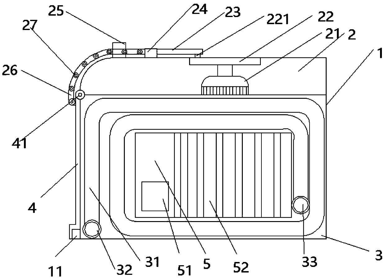
[0022] An engine cover of construction machinery, comprising: a housing 1, a power chamber 2, a cooling plate 3 and a sliding door 4, such as figure 1 As shown, the upper end of the housing 1 is a power chamber, the lower end is a cooling plate 3, a motor 21 is arranged in the power chamber 2, a turntable 22 is arranged at the upper end of the motor 21, and a turntable connection block 221 is arranged on the turntable 22, and the turntable connection block 221 passes through The connecting column 23 is rotationally connected with the connecting column 23, and the left side of the connecting column 23 passes through the first-level limiting groove 24 and is rotatably connected with the lock block 26. The left side of the first-level limiting groove 24 is provided with a second-level limiting groove 25 and the power chamber 2 Fixedly connected, the lock blocks 26 are rotatably connected by the lock ring 27, the lower end of the lock block 26 is rotatably connected with the slidin...

Embodiment 2

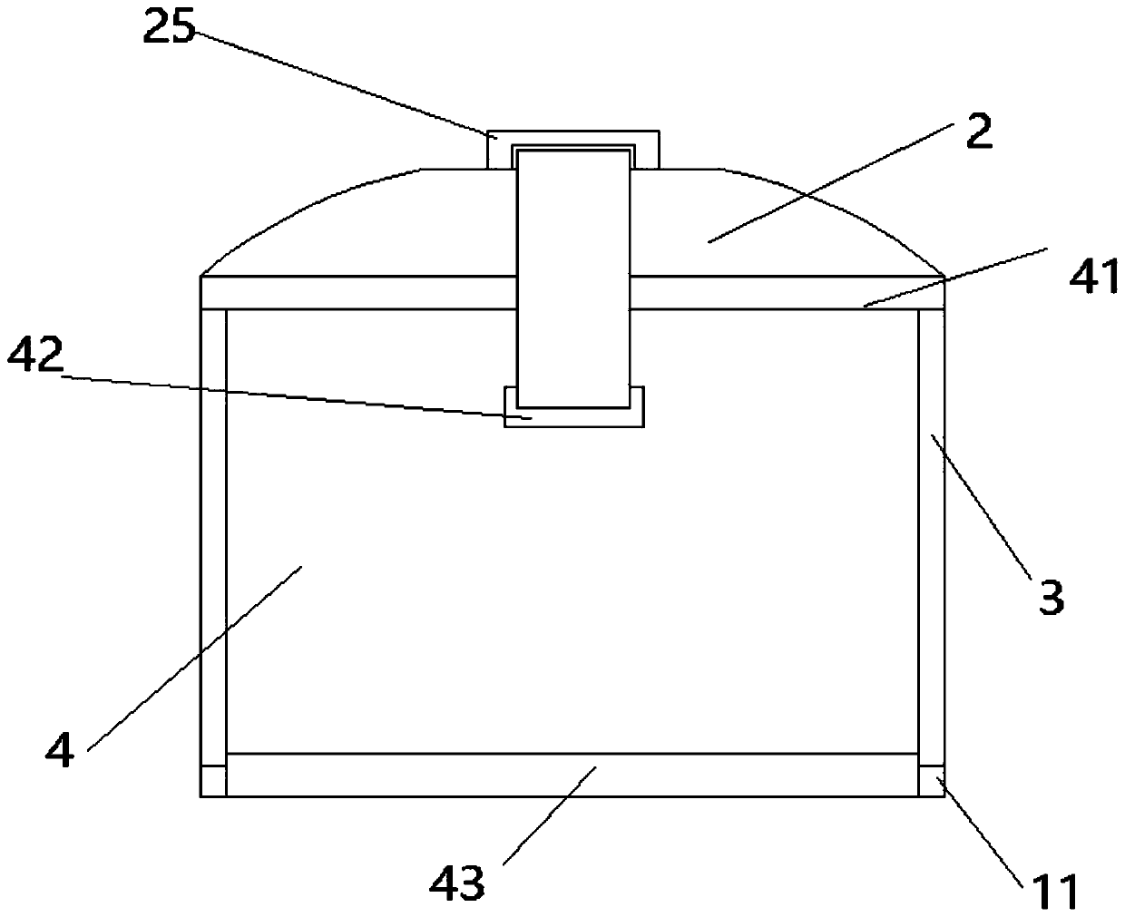
[0024] The difference between this embodiment and embodiment 1 is that, as Figure 4 As shown, the lower end of the connecting column 23 is connected to the rotating shaft 28, and the lower end of the rotating shaft 28 is fixedly connected with the locking block 26. The primary limiting column 24 and the secondary limiting groove 25 are provided with sliding holes, and the connecting column 23, the rotating shaft 28 and the locking block 26 Pass through the sliding hole in the primary limiting frame 24.

Embodiment 3

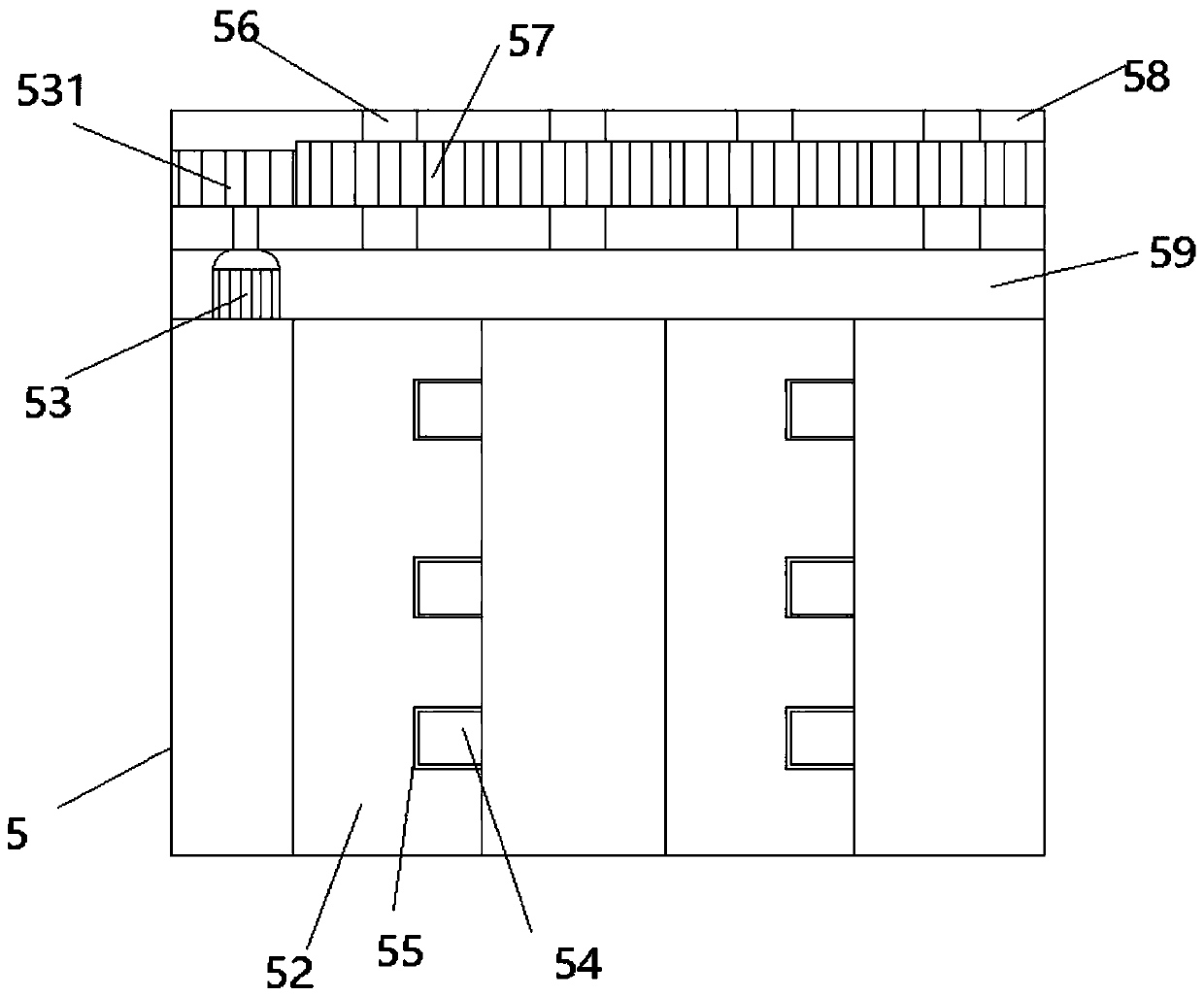
[0026] The difference between this embodiment and Embodiment 1 is that the upper end of the ventilation device 5 is provided with a power layer 58, and the power layer 58 is provided with a number of blade columns 56, and the blade column 56 is provided with a fan impeller 57, and the lower end of the power layer 58 is The motor layer 59 is provided with a fan blade motor 53 inside the motor layer 59, the upper end of the fan blade motor 53 is connected to the motor wheel 531, the fan blade motor wheel 531 is fitted with the fan blade wheel 57, and the lower end of the fan blade column 56 is fixedly connected with the fan blade 52, The right end of the left fan blade 52 is provided with a fan blade locking slot 55 , and the left side of the right fan blade 52 is provided with a fan blade locking block 54 .

[0027] During use, the blade motor 53 rotates the blade motor wheel 531, the blade motor wheel 531 drives the fan wheel 57 to rotate, and the fan wheel 57 drives the fan bl...


PUM


Abstract

The invention provides an engine hood of an engineering machine, which includes a housing, power chambers, cooling plates and sliding doors; an upper end of that house is a power chamer, lower end iscooling plate, motor in power room, an upper end of that motor is provide with a rotary table, a turntable connecting block is arranged on the turntable, a link block of that rotary table is rotatablyconnected with the connecting column through the connecting column, a left side of that connecting post is rotatably connected with the locking block through a first limiting groove, a locking blockis rotatably connected with each other through a locking ring, a low end of that lock block is rotatably connected with the pull door lock, the sliding door lock is fixedly connected with the slidingdoor, an upper end of that sliding door is rotatably connected with the housing through a sliding door shaft, a low end of that sliding door is provide with a sliding door base, A liquid inlet is arranged in that lower left corner of the cooling plate, an infusion pipe is arranged in the liquid inlet, the other end of the infusion pipe is connected with the liquid outlet, a ventilation device is arrange in the middle of the cooling plate, a controller is arranged on the left side of the ventilation device, and a ventilation fan blade is arranged on the right side of the ventilation device. Thedevice is simple in use, effectively dissipates heat and lowers temperature to the engine, and is safe in operation.

Description

technical field [0001] The invention relates to the technical field of engineering machinery, in particular to an engine cover of an engineering machinery. Background technique [0002] Generally, the engine tends to generate heat and heat after a long time of operation. When the engine is idle, it is easy to get dust. When it is used again, the efficiency of the engine is not as good as before. Many existing hoods wrap the engine and set ventilation on the side. Although the effect of heat dissipation can be achieved in this way, the cooling effect is not good. At the same time, the temperature of the engine hood increases due to the engine's long-term operation, which often causes burns. Contents of the invention [0003] The technical problem to be solved by the present invention is to provide an engine cover of construction machinery to solve the problems raised in the above-mentioned background technology. [0004] The technical problem solved by the present inventio...

Claims


Application Information

Patent Timeline
Patent Type & Authority Patents(China)
IPC IPC(8): B62D25/10B60K11/02
CPCB60K11/02B62D25/10
Inventor 许炳初
Owner 台州市黄岩森亨工艺礼品厂
Why Eureka
Try Eureka