

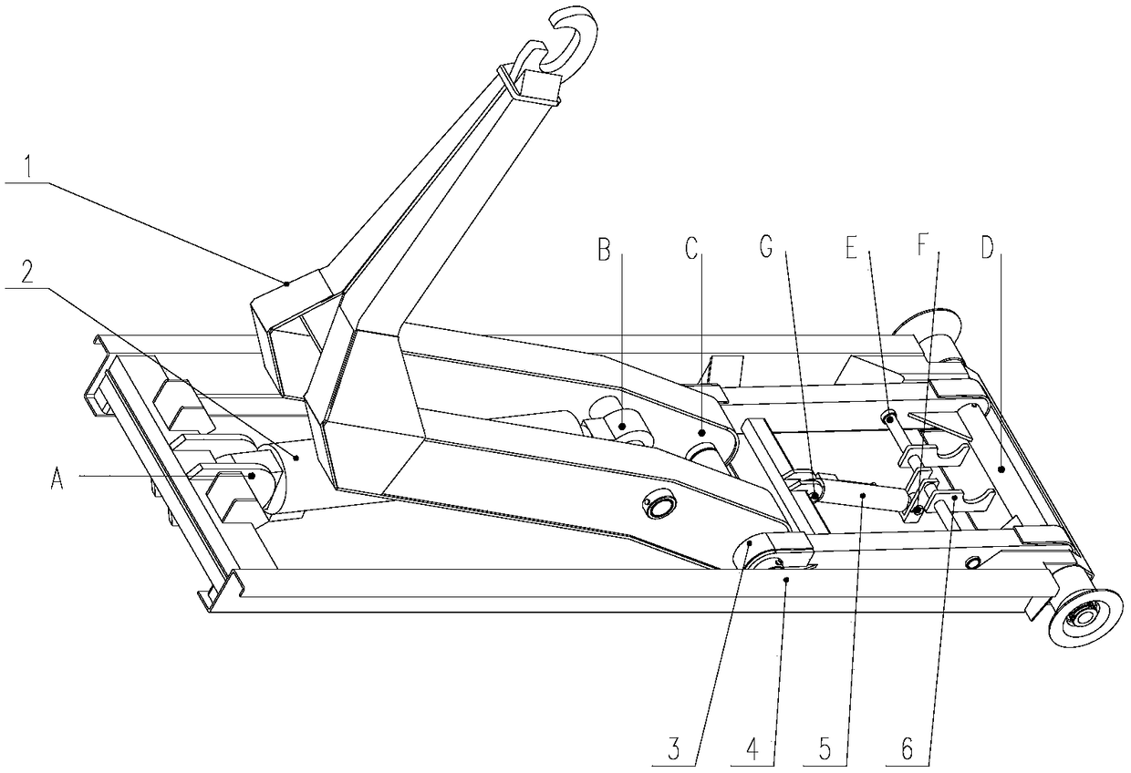
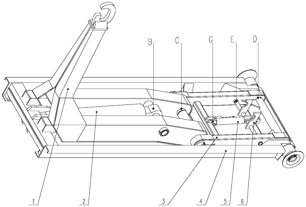
Draw arm device of single-cylinder draw arm type garbage truck
A garbage truck and arm-type technology, applied in the field of sanitation vehicles, can solve the problems of damage to the connecting shaft and the pull arm structure, the inability of the hydraulic cylinder to move synchronously, the damage to the structure of the garbage bin, etc. Effect of tight contact area
- Summary
- Abstract
- Description
- Claims
- Application Information
AI Technical Summary
Problems solved by technology
Method used
Image

Examples
Embodiment Construction
[0015] In order to make the purpose, technical solutions and advantages of the embodiments of the present invention clearer, the technical solutions in the embodiments of the present invention will be clearly and completely described below in conjunction with the drawings in the embodiments of the present invention. Obviously, the described embodiments It is a part of embodiments of the present invention, but not all embodiments.
[0016] In describing the present invention, it is to be understood that the terms "radial", "axial", "upper", "lower", "top", "bottom", "inner", "outer" etc. indicate orientation Or the positional relationship is based on the orientation or positional relationship shown in the drawings, which is only for the convenience of describing the present invention and simplifying the description, and does not indicate or imply that the referred device or element must have a specific orientation, be constructed and operated in a specific orientation , and the...
PUM
 Abstract
Description
Claims
Application Information