Antenna information sensing unit mounting bracket, antenna information sensing unit and antenna system

A technology for sensing unit and antenna information, which is applied to antenna supports/installation devices, antennas, antenna components, etc., can solve the problem of not meeting the accuracy requirements of antenna information parameters, and achieves the stability and position of the mounting bracket of the antenna information sensing unit. Precise, adjustable and stable effect

Active Publication Date: 2018-12-11
HUAWEI TECH CO LTD
4 Cites 1 Cited by

AI-Extracted Technical Summary

Problems solved by technology

[0004] However, the above manual measurement method can no longer meet the accuracy requirements of antenna info...

Method used

[0074] The embodiment of the present application sets the antenna information sensing unit 1 through the antenna information sensing unit mounting bracket 2 on the antenna 3, so that the information parameters of the antenna 3 can be obtained in real time, so as to meet the requirements of wireless communication network optimization and network planning and design. The accuracy requirements of the antenna information parameters.
[0090] The clamping part of the embodiment of the present application adopts the structure shown in FIG. 5A and FIG. 5...

Abstract

An embodiment of the present application provides an antenna information sensing unit mounting bracket, an antenna information sensing unit, and an antenna system. A support for mount an antenna information sensing unit include a main wishbone, a first clamping member and a second clamping member; The main wishbone is respectively connected with the first clamping member and the second clamping member, and the distance between the first clamping member and the second clamping member is adjustable; The first clamping member and the second clamping member are used for fixing the main wishbone tothe top of the antenna, wherein the main wishbone is used for connecting with the antenna information sensing unit. The first clamping member and the second clamping member are used for fixing the main wishbone to the top of the antenna. Embodiments of the present application can realize that an antenna information sensing unit is provided on the antenna, parameter information of the antenna, such as a mechanical angle, an azimuth angle, and the like, can be obtained in real time, and different antenna sizes can be adapted due to the distance adjustable before the antenna information sensingunit mounts the first clamping member and the second clamping member of the bracket.

Application Domain

Technology Topic

Image

  • Antenna information sensing unit mounting bracket, antenna information sensing unit and antenna system
  • Antenna information sensing unit mounting bracket, antenna information sensing unit and antenna system
  • Antenna information sensing unit mounting bracket, antenna information sensing unit and antenna system

Examples

  • Experimental program(1)

Example Embodiment

[0071] In order to make the purpose, technical solutions, and advantages of the embodiments of the present application clearer, the technical solutions in the embodiments of the present application will be described clearly and completely in conjunction with the drawings in the embodiments of the present application.
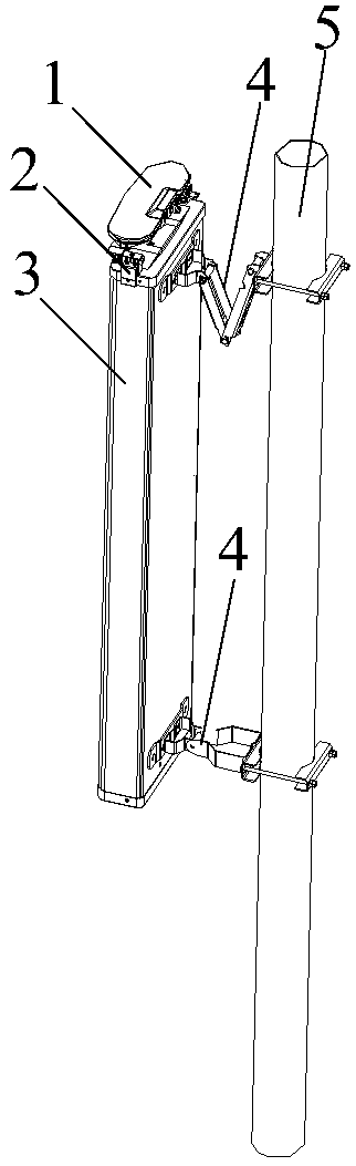
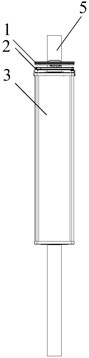
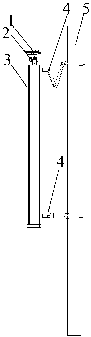
[0072] Figure 1A This is a schematic diagram of a three-dimensional structure of an antenna system according to an embodiment of this application, Figure 1B for Figure 1A The front view of the antenna system shown, Figure 1C for Figure 1A The side view of the antenna system shown, such as Figure 1A , Figure 1B as well as Figure 1C As shown, the antenna system may specifically include an antenna information sensing unit 1 (Antenna Information Sensor Unit, AISU for short), an antenna information sensing unit mounting bracket 2, an antenna 3, an antenna mounting bracket 4, and an antenna mounting pole 5. The sensing unit 1 is arranged on the upper end cover of the antenna 3 through the antenna information sensing unit mounting bracket 2. As an optional connection method, the antenna 3 is set on the antenna mounting pole 5 through the antenna mounting bracket 4. Of course, it is understandable that the specific setting method of the antenna can also be in other ways. This is only an example for illustration. , The embodiments of this application are not limited by this.
[0073] The antenna information sensing unit 1 is used to obtain information parameters of the antenna 3 in real time, and the information parameters include mechanical inclination, azimuth, latitude and longitude, and antenna installation height (hanging height). Specifically, the antenna information sensing unit 1 may specifically include two Global Positioning System (GPS) antennas, an acceleration sensor, a control board, and an interface. Specifically, the azimuth angle, latitude and longitude, and antenna installation height of the antenna 3 can be measured through two GPS antennas, and the mechanical inclination angle of the antenna 3 can be measured through an acceleration sensor.
[0074] In the embodiment of the present application, the antenna information sensing unit 1 is installed on the antenna 3 through the antenna information sensing unit mounting bracket 2, so that the information parameters of the antenna 3 can be obtained in real time to meet the requirements of the antenna in the process of wireless communication network optimization and network planning and design. The accuracy requirements of the information parameters.
[0075] The embodiments of the present application will explain in detail how the antenna information sensing unit 1 is installed on the antenna through the antenna information sensing unit mounting bracket 2 through the explanation of the following embodiments.
[0076] figure 2 This is a schematic structural diagram of an antenna information sensing unit mounting bracket 2 according to an embodiment of this application, such as figure 2 As shown, the antenna information sensing unit mounting bracket 2 may specifically include a main cross arm 21, a first clamping member 22 and a second clamping member 23. The main cross arm 21 is respectively connected with the first clamping member 22 and the second clamping member 23. The distance between the first clamping member 22 and the second clamping member 23 is adjustable. The holding member 22 and the second clamping member 23 are used to fix the main cross arm 21 on the top of the antenna, wherein the main cross arm 21 is used to connect with the antenna information sensing unit 1.
[0077] Specifically, the antenna information sensing unit 1 is connected to the main cross arm 21. When the antenna information sensing unit mounting bracket of the embodiment of the present application is set on the antenna, the first clamp 22 and the second clamp can be adjusted according to the size of the antenna. The distance between the holding parts 23 is further clamped by the first holding part 22 and the second holding part 23, so that the main cross arm 21 is fixed on the antenna, so that the antenna information sensing unit is set on the antenna to obtain real-time information. The parameter information of the antenna, such as mechanical angle, azimuth angle, etc., and since the distance between the first clamping member 22 and the second clamping member 23 can be adjusted, it can be adapted to different antenna sizes.
[0078] There are many ways to realize the adjustable distance between the first clamping member 22 and the second clamping member 23, image 3 That is, it is an achievable manner. For specific implementation manners, refer to the specific explanations of the following embodiments.
[0079] image 3 This is a schematic diagram of the split structure of an antenna information sensing unit mounting bracket 2 according to an embodiment of this application, such as image 3 Shown in figure 2 On the basis of the antenna information sensing unit mounting bracket 2 shown, the antenna information sensing unit mounting bracket 2 may further include: a sliding mounting arm 24 and a first fastener 25. The first clamping member 22 is provided at one end of the main cross arm 21, the second clamping member 23 is disposed at one end of the sliding mounting arm 24, and the main horizontal arm 21 is provided with a sliding slide for the sliding mounting arm 24 to slide. Slot 211, the first fastener 25 is used to connect the main cross arm 21 and the main cross arm 21 with the first fastener 25 when the first clamp 22 and the second clamp 23 are clamped on the antenna The sliding mounting arm 24 is fixedly connected.
[0080] Specifically, there are many specific implementation ways for the second clamping member 23 to be arranged at one end of the sliding mounting arm 24. For example, the second clamping member 23 can be fixed to the sliding mounting arm 24 by fixing members such as screws or bolts. One end. Of course, it can be understood that the second clamping member 23 can also be fixed to one end of the sliding mounting arm 24 by welding. The embodiments of this application do not illustrate this one by one. Similar to the arrangement of the second clamping member 23, the first clamping member 22 can also be fixed to one end of the main cross arm 21 by fixing members such as screws, bolts, etc., and the first clamping member 22 can also be fixed by welding. At one end of the main cross arm 21, this embodiment of the present application does not illustrate this one by one. In the embodiment of the present application, the distance between the first clamping member 22 and the second clamping member 23 can be adjusted in a specific implementation manner: the main transverse arm is provided with a sliding groove 211 for the sliding mounting arm 24 to slide, so as to pass By adjusting the position of the sliding mounting arm 24 in the sliding groove of the main cross arm 21, the distance between the first clamping member 22 and the second clamping member 23 can be adjusted. That is, the sliding mounting arm 24 is placed in the sliding groove 211, and the position of the sliding mounting arm 24 in the sliding groove of the main cross arm 21 is adjusted by pulling. When adjusted to an appropriate position, the first fastener 25 The main cross arm and the sliding mounting arm are fixedly connected, so that different antenna sizes can be adapted, and the antenna information sensing unit can be installed on the antenna through the antenna information sensing unit mounting bracket.
[0081] The number of sliding grooves 211 may be one or more, and the shape of the sliding mounting arm 24 is adapted to the sliding groove of the main cross arm 21. For example, the number of sliding grooves 211 is four, and every two of them are arranged up and down. Then, the side shape of the sliding mounting arm can be as Figure 4 As shown, the four protrusions in the horizontal direction are respectively clamped in the sliding groove of the main cross arm. The more the number of sliding grooves is set, the more stable the adjustment and the more accurate the position when adjusting the distance between the first clamping part and the second clamping part of the antenna information sensing unit mounting bracket of the embodiment of the present application.
[0082] There are many specific structures of the first clamping member 22 and the second clamping member 23, which can be flexibly set according to requirements. Figure 4 That is, it is an achievable way, and the specific structure can refer to the specific explanation of the following embodiments.
[0083] Figure 5A This is a schematic diagram of a three-dimensional structure of a clamping piece according to an embodiment of the present application, Figure 5B for Figure 5A A side view of the clamping member shown, the first clamping member 22 and the second clamping member 23 can adopt the same structure, that is, both adopt the following Figure 5A with Figure 5B The structure shown, such as Figure 5A with Figure 5B As shown, the clamping member (the first clamping member 22 or the second clamping member 23) may include a rectangular fixing frame 201, a fixing member 202, an L-shaped positioning plate 203 and a hook 204. The top end of the rectangular fixing frame 201 and the The first folded edge 2031 of the L-shaped positioning plate 203 is provided with a first through hole through which the fixing member 202 passes. The first folded edge 2031 is connected to the fixing member 202, and the first folded edge 2031 passes through the fixing member 202. Fixed in the rectangular fixing frame 201, the second folded edge 2032 of the L-shaped positioning plate 203 is connected to the hook 204, and the hook 204 is used for clamping on the top of the antenna.
[0084] Among them, the L-shaped positioning plate 203 and the hook 204 can be an integrated workpiece, or Figure 5A with Figure 5B As shown, the hook 204 is fixed on the second flange 2032 of the L-shaped positioning plate 203 by screws. The knife edge of the hook 204 can be clamped between the upper end cover of the antenna and the radome. The mounting bracket of the antenna information sensing unit of the embodiment is fixed on the antenna. The specific arrangement may be that the two clamping pieces are respectively clamped on both sides of the top of the antenna. However, by rotating the fixing piece 202, the position of the L-shaped positioning plate 203 in the rectangular fixing frame 201 is adjusted to make the rectangular The bottom surface of the fixing frame 201 is in contact with the top of the antenna, that is, the fixing member 202 and the L-shaped positioning plate 203 can be screwed, and the position height of the L-shaped positioning plate 203 can be raised or lowered by rotating the fixing member 202, so that it is suitable for different antennas. The size of the hood.
[0085] Optionally, the inner side of the rectangular fixed frame 201 further includes N guide posts 2011, the L-shaped positioning plate 203 also includes N guide through holes matching the guide posts 2011, and each guide post 2011 penetrates the corresponding guide through hole. Inside the hole, where N is an integer greater than zero. The guide post can play a guiding role when assembling the L-shaped positioning plate 203.
[0086] From Figure 5A It can be seen that the upper end of the guide post 2011 is connected to the top end of the rectangular fixed frame 201, and the lower end of the guide post 2011 is not connected to the bottom end of the rectangular fixed frame 201. There is a preset distance between the two, which is used to connect the L-shaped positioning plate 203 is set in the rectangular fixed frame 201 from the spaced position. That is, the various components of the clamping member in this embodiment are detachable.
[0087] It should be noted that both the first clamping member 22 and the second clamping member 23 of the embodiment of the present application can be used Figure 5A with Figure 5B As shown in the clamping member, since the first clamping member 22 is connected to the main cross arm 21, the second clamping member 23 is connected to the sliding mounting arm 24, and because the main cross arm 21 and the sliding mounting arm 24 have different structures, In such Figure 5A with Figure 5B One side of the rectangular fixing frame 201 of the clamp shown is provided with a clamping portion 2014 and the other side is provided with a connecting portion 2013.
[0088] Wherein, the clamping portion 2014 is connected to the main cross arm 21, that is, the clamping piece is used as the first clamping piece. Optionally, the main cross arm 21 may also be provided with a groove, and the clamping portion 2014 is connected to the groove for The first clamping member is fixed on the main cross arm 21. In another implementation manner, the clamping portion 2014 can be disposed in the sliding groove 211 of the main cross arm, which is not limited in the embodiment of the present application. Optionally, a fixing portion 2012 may be further provided under the clamping portion 2014, and the fixing portion 2012 is provided with a through hole, and the first clamping member is further fixed by screws.
[0089] Wherein, the connecting portion 2013 is connected to the sliding mounting arm 24, that is, the clamping piece is used as the second clamping piece. In an optional embodiment, the connecting portion 2013 is provided with at least one through hole, and the connecting portion 2013 can be connected to The sliding mounting arm 24 is connected.
[0090] The clamping piece of the embodiment of the application adopts such as Figure 5A with Figure 5B The structure shown makes the assembly more flexible when installing the mounting bracket of the antenna information sensing unit of the embodiment of the present application, and the implementation cost is low.
[0091] Figure 6A with Figure 6B That is, it is another achievable way to realize that the distance between the first clamping member 22 and the second clamping member 23 can be adjusted. For specific implementation, please refer to the specific explanation of the following embodiments.
[0092] Figure 6A This is a schematic diagram of the three-dimensional structure of another antenna information sensing unit mounting bracket 2 according to an embodiment of the present application. Figure 6B for Figure 6A A side view of the mounting bracket 2 of the antenna information sensing unit as shown, as Figure 6A with Figure 6B As shown, the antenna information sensing unit mounting bracket of this embodiment includes a main horizontal arm 21, a first clamping member 22, a second clamping member 23, a first installation vertical arm 26, a second installation vertical arm 27, and at least one Two fasteners 28 and at least one third fastener 28. Wherein, the first clamping member 22 is connected to the main horizontal arm 21 through at least one second fastener 28 and the first vertical mounting arm 26. The second clamping member 23 is connected to the main horizontal arm 21 through at least one third fastener 29 and the second vertical mounting arm 27. The at least one second fastener 28 and the at least one third fastener 29 are used to pass the at least one first clamping member 22 and the second clamping member 23 on the antenna. The two fasteners 28 and the at least one third fastener 29 fix the main cross arm 21 on the top of the antenna.
[0093] It should be noted that the first vertical mounting arm 26 and the second vertical mounting arm 27 can also be adjusted. Specifically, they can be adjusted on the lower main cross arm. The adjustment is usually used for large-scale adjustments. For fine adjustments, you can adjust the second Fastener 28 or third fastener 29. Among them, the second fastener and the third fastener may specifically be adjustable handles.
[0094] In an implementation manner, the first clamping member 22 is provided with a second through hole 2201 for piercing the at least one second fastener 28, and the second clamping member 23 is provided with a second through hole 2201 for piercing the at least one first fastener. The third through hole 2301 of the three fastener 29. One end of the first vertical mounting arm 26 is adjustably connected to the main cross arm 21, and at least one second fastener penetrates 28 through the second through hole 2201 to connect the first vertical mounting arm 26 with the first The clamping member 22 is connected. One end of the second vertical mounting arm 29 is adjustably connected to the main horizontal arm 21, and the at least one third fastener 29 is inserted through the third through hole 2301 to connect the second vertical mounting arm 27 is connected to the second clamping member 23.
[0095] Optionally, the antenna information sensing unit mounting bracket 2 may further include at least one clamping member, and the at least one clamping member is respectively arranged on the second fastener and the third fastener, so The at least one clamping member is used for fixedly connecting the at least one second fastener with the first clamping member, and fixedly connecting the at least one third fastener with the second clamping member.
[0096] The specific implementation manner of the adjustable distance between the first clamping member 22 and the second clamping member 23 in the embodiment of the present application may be to provide a second fastener and a third fastener, so as to adjust the second fastening The distance between the first clamping member 22 and the second clamping member 23 can be adjusted. Therefore, different antenna sizes can be adapted, and the antenna information sensing unit can be installed on the antenna through the antenna information sensing unit mounting bracket.
[0097] On the basis of the above embodiments, the antenna information sensing unit mounting bracket 2 and the antenna information sensing unit 1 can be connected in many ways. Among them, in order to realize the detachable connection of the antenna information sensing unit, the antenna information sensing unit It can be maintained or replaced separately, and in the embodiment of the present application, a mounting seat may also be provided on the antenna information sensing unit bracket of the foregoing embodiment. For details, refer to the specific explanation of the following embodiment.
[0098] Figure 7A This is a schematic diagram of a three-dimensional structure of another antenna information sensing unit mounting bracket according to an embodiment of this application, Figure 7B for Figure 7A The front view of the mounting bracket of the antenna information sensing unit shown, Figure 7C for Figure 7A The rear view of the mounting bracket of the antenna information sensing unit shown, such as Figure 7A to Figure 7C As shown, the main cross arm 21 is also provided with a mounting base 30, which is used to connect with the mounting slide at the bottom of the antenna information sensing unit, and fix the antenna information sensing unit 1 on the antenna information sensing unit. The sensing unit is installed on the bracket 2.
[0099] An optional implementation method, the mounting seat such as Figure 7A As shown, the mounting seat includes a base 301 and sliding grooves 302 provided on both sides of the base. The base 301 is fixedly connected to the main cross arm 21, and the sliding groove 302 is used to connect to the mounting sliding member. In a sliding connection, the base is further provided with M threaded holes 303, the M threaded holes 303 are arranged in a horizontal direction, and the M threaded holes 303 are used to connect with the L-shaped limit seat of the mounting slide.
[0100] The mounting bracket of the antenna information sensing unit of this embodiment can realize the detachable connection of the antenna information sensing unit, so that the antenna information sensing unit can be maintained or replaced separately.
[0101] Figure 8A This is a schematic diagram of a three-dimensional structure of an antenna information sensing unit according to an embodiment of this application, Figure 8B for Figure 8A The front view of the antenna information sensing unit shown, Figure 8C for Figure 8A The rear view of the antenna information sensing unit shown, such as Figure 8A to Figure 8C As shown, the antenna information sensing unit may include an antenna information sensing unit body 11 and a mounting slider 12, the mounting slider 12 is arranged at the bottom of the antenna information sensing unit body 11, and the mounting slider 12 is used for mounting with the antenna information sensing unit The mounting base 30 of the bracket 2 is connected to fix the antenna information sensing unit body 11 on the antenna information sensing unit mounting bracket 2.
[0102] Optionally, the mounting slide 12 may include a top surface 121 and two L-shaped sliding parts 122, the top surface 121 is fixedly connected to the antenna information sensing unit body 11, and the two L-shaped sliding parts are respectively Connected to both ends of the top surface, the two L-shaped sliding parts are used for sliding connection with the mounting seat 30 of the antenna information sensing unit mounting bracket 2. The mounting slide 12 may also include M L-shaped limit seats 123, the M L-shaped limit seats 123 are arranged in a horizontal direction, and the M L-shaped limit seats 123 are used to interact with the mounting seat. 30 threaded hole connection. Wherein, the L-shaped limiting seat 123 may specifically include an L-shaped limiting body and a fixing member. The L-shaped limiting body is provided with a through hole penetrating the fixing member, and the fixing member may be a screw. The fixing member can be connected with the threaded hole 303.
[0103] The antenna information sensing unit of the embodiment of the present application can be set on the antenna, so that the information parameters of the antenna 3 can be obtained in real time, so as to meet the accuracy requirements of the antenna information parameters in the process of wireless communication network optimization and network planning and design.
[0104] In addition, the antenna information sensing unit of this embodiment can realize the detachable connection of the antenna information sensing unit, so that the antenna information sensing unit can be maintained or replaced separately.
[0105] Figure 9A This is an assembly schematic diagram of an antenna information sensing unit mounting bracket and an antenna information sensing unit according to an embodiment of this application, Figure 9B This is a front view of a completed assembly of an embodiment of this application, Figure 9C This is an assembled rear view of the embodiment of this application, such as Figure 9A to Figure 9C As shown, the mounting bracket of the antenna information sensing unit specifically adopts Figure 7A to Figure 7C The antenna information sensing unit sensing bracket structure shown, the antenna information sensing unit specifically adopts such as Figure 8A to Figure 8C The antenna information sensing unit structure shown. Such as Figure 9A As shown, during the assembly process, the mounting sliding member 12 at the bottom of the antenna information sensing unit can be slidably installed into the mounting seat 30 of the antenna information sensing unit mounting bracket, and can be fastened by screw connection.
[0106] Picture 10 This is a schematic structural diagram of another antenna system according to an embodiment of this application, such as Picture 10 As shown, the antenna system includes: antenna 3, antenna information sensing unit 1, and antenna information sensing unit mounting bracket 2, wherein the antenna information sensing unit mounting bracket adopts Figure 6A with Figure 6B The structure shown. Its implementation principle and technical effect are similar, and will not be repeated here.
[0107] Finally, it should be noted that the above embodiments are only used to illustrate the technical solutions of the application, not to limit it; although the application has been described in detail with reference to the foregoing embodiments, those of ordinary skill in the art should understand: It is still possible to modify the technical solutions described in the foregoing embodiments, or equivalently replace some or all of the technical features; these modifications or replacements do not make the essence of the corresponding technical solutions deviate from the technical solutions of the embodiments of the application range.

PUM

no PUM

Description & Claims & Application Information

We can also present the details of the Description, Claims and Application information to help users get a comprehensive understanding of the technical details of the patent, such as background art, summary of invention, brief description of drawings, description of embodiments, and other original content. On the other hand, users can also determine the specific scope of protection of the technology through the list of claims; as well as understand the changes in the life cycle of the technology with the presentation of the patent timeline. Login to view more.

Similar technology patents

Height-adjustable display

Owner:天玑智谷(湖北)信息技术有限公司

CMOS band-gap reference source circuit

Owner:安特(苏州)半导体有限公司

Tool bit service life testing device of ultrasonic knife

PendingCN112268819ASmooth reciprocating motionRegulation stabilityMaterial strength using repeated/pulsating forcesElectric machineryDrive motor
Owner:CHANGZHOU ANKANG MEDICAL EQUIP

Classification and recommendation of technical efficacy words

  • Regulation stability
  • Accurate location
Why Eureka
Try Eureka