
Cutter of mower

A lawn mower and cutter shaft technology, which is applied to harvesters, cutters, agricultural machinery and implements, etc., can solve problems such as missed cuts and uneven cuts, and achieve the effect of ensuring consistency

Active Publication Date: 2018-12-14
HUAIYIN INSTITUTE OF TECHNOLOGY
View PDF2 Cites 0 Cited by
  • Summary
  • Abstract
  • Description
  • Claims
  • Application Information

AI Technical Summary

Problems solved by technology

[0004] The current lawn mower uses a cutting knife, because the kinetic energy of the cutting knife rotating near the connection position between the knife shaft and the rotating knife is small during the rotary mowing process, it is easy to miss the cut and the problem of uneven cutting

Method used


Image

  • Cutter of mower
  • Cutter of mower
  • Cutter of mower

Examples


Embodiment 1

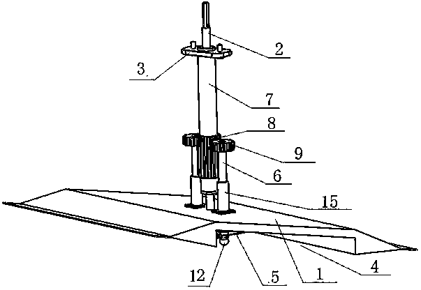
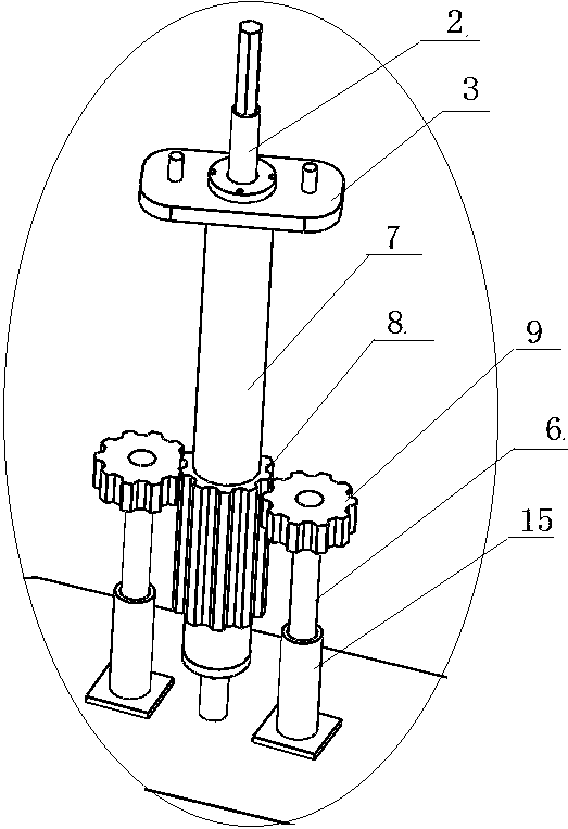
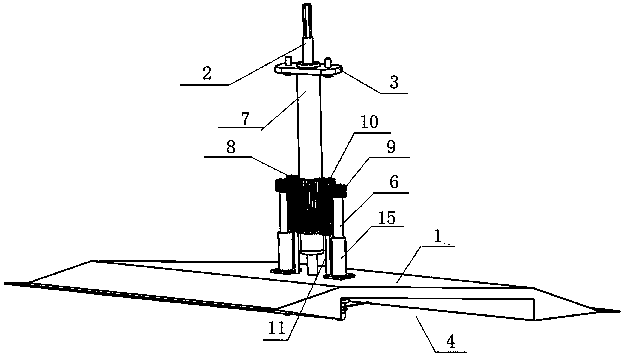
[0036] Such as figure 1 , 2 As shown in , 5, a cutting knife of a lawn mower comprises a knife body 1 positioned below the lawn mower and rotates horizontally around the knife axis A2, and the knife shaft A2 is fixed with the knife body 1 and is rotatably connected with the lawn mower ; The coaxial sleeve on the cutter shaft 2 is provided with a shaft sleeve 7, the top of the shaft sleeve 7 is fixed with the lawn mower through the connector 3, and the top of the cutter shaft A2 passes through the connector 3 upwards, and is fixed with The transmission device of the driving device of the lawn mower, the auxiliary knife 5 is connected to the horizontal rotation below the knife body 1, and the auxiliary knife 5 is located at the bottom of the knife body 1. The cutter shaft B6 of the cutter 5 passes through the cutter body 1 upwards and is connected to the shaft sleeve 7 in a transmission manner. The auxiliary cutter 5 is fixedly connected to the cutter shaft B6. The position sl...

Embodiment 2

[0039] Such as image 3 , 4As shown in , 5, a cutting knife of a lawn mower comprises a knife body 1 positioned below the lawn mower and rotates horizontally around the knife axis A2, and the knife shaft A2 is fixed with the knife body 1 and is rotatably connected with the lawn mower ; The coaxial sleeve on the cutter shaft 2 is provided with a shaft sleeve 7, the top of the shaft sleeve 7 is fixed with the lawn mower through the connector 3, and the top of the cutter shaft A2 passes through the connector 3 upwards, and is fixed with The transmission device of the driving device of the lawn mower, the auxiliary knife 5 is connected to the horizontal rotation below the knife body 1, and the auxiliary knife 5 is located at the bottom of the knife body 1. The cutter shaft B6 of the cutter 5 passes through the cutter body 1 upwards and is connected to the shaft sleeve 7 in a transmission manner. The auxiliary cutter 5 is fixedly connected to the cutter shaft B6. The position sle...


PUM


Abstract

The invention discloses a cutter of a mower. The cutter comprises a cutter body which is arranged under the mower and horizontally rotates around a cutter shaft A, wherein the cutter shaft A is fixedto the cutter body and is rotatably connected with the mower, the cutter shaft is coaxially sleeved by a shaft sleeve, and the shaft sleeve is fixed to the mower; and an auxiliary knife is connected to the lower part of the cutter body in a horizontal and rotary mode, a cutter shaft B of the auxiliary knife passes through the cutter body and is connected with the shaft sleeve in a transmission mode, and the auxiliary knife is fixedly connected with the cutter shaft B. By installing the auxiliary knife at the lower part of the cutter body, secondary cutting can be performed on positions which have easy cutting leakage in the central area of the lower part of the cutter body, so that no phenomena of cutting leakage of the lower part of the cutter body are ensured.

Description

technical field [0001] The invention relates to a lawnmower, in particular to a cutting knife of the lawnmower. Background technique [0002] Lawn mower (Lawn mowCr) is also known as weeder, lawnmower, lawn trimmer and so on. A lawn mower is a mechanical tool for mowing lawns, vegetation, etc. It is composed of a cutter head, an engine, a walking wheel, a walking mechanism, a blade, a handrail, and a control part. [0003] The cutterhead is installed on the walking wheel, the cutterhead is equipped with an engine, and the output shaft of the engine is equipped with a blade. The blade uses the high-speed rotation of the engine to increase the speed a lot, which saves the working time of the weeding workers and reduces a lot of human resources. [0004] In the current lawn mower, the mowers used have less kinetic energy in the vicinity of the connection position between the knife shaft and the rotary knife during the rotary mowing process, so missing cuts and uneven cutting a...

Claims


Application Information

Patent Timeline
Patent Type & Authority Applications(China)
IPC IPC(8): A01D34/68A01D34/685A01D34/73
CPCA01D34/6806A01D34/685A01D34/73
Inventor 孙金超赵庆娟张红胜潘泽源
Owner HUAIYIN INSTITUTE OF TECHNOLOGY
Learn More