Mutual scraping cycloid wheel feeding device

A technology of feeding device and cycloid wheel, which is used in transportation and packaging, rotary conveyors, conveyors, etc., can solve the problems of decreasing output, troublesome cleaning, easy adhesion, etc., to prevent material accumulation and return. Flow, long service life and reliable operation

Active Publication Date: 2020-09-08
CHANGZHOU UNIV
View PDF10 Cites 0 Cited by
  • Summary
  • Abstract
  • Description
  • Claims
  • Application Information

AI Technical Summary

Problems solved by technology

[0004] The purpose of the present invention is to solve the problems of the existing rotary feeding device, such as easy adhesion, jamming, decreasing output volume, troublesome cleaning, etc., when conveying high-viscosity materials, and to provide a device that utilizes the claw tip at the discharge port. The new mutual scraping rotary feeding device can "scrape" the groove surface of the feed tray and the feed tray can also "scrape" the claw surface

Method used


Image

  • Mutual scraping cycloid wheel feeding device
  • Mutual scraping cycloid wheel feeding device
  • Mutual scraping cycloid wheel feeding device

Examples


Embodiment Construction

[0018] The present invention will be further described below in conjunction with the accompanying drawings.

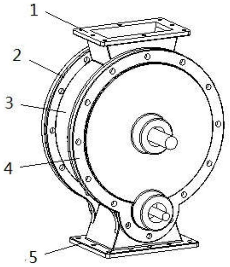
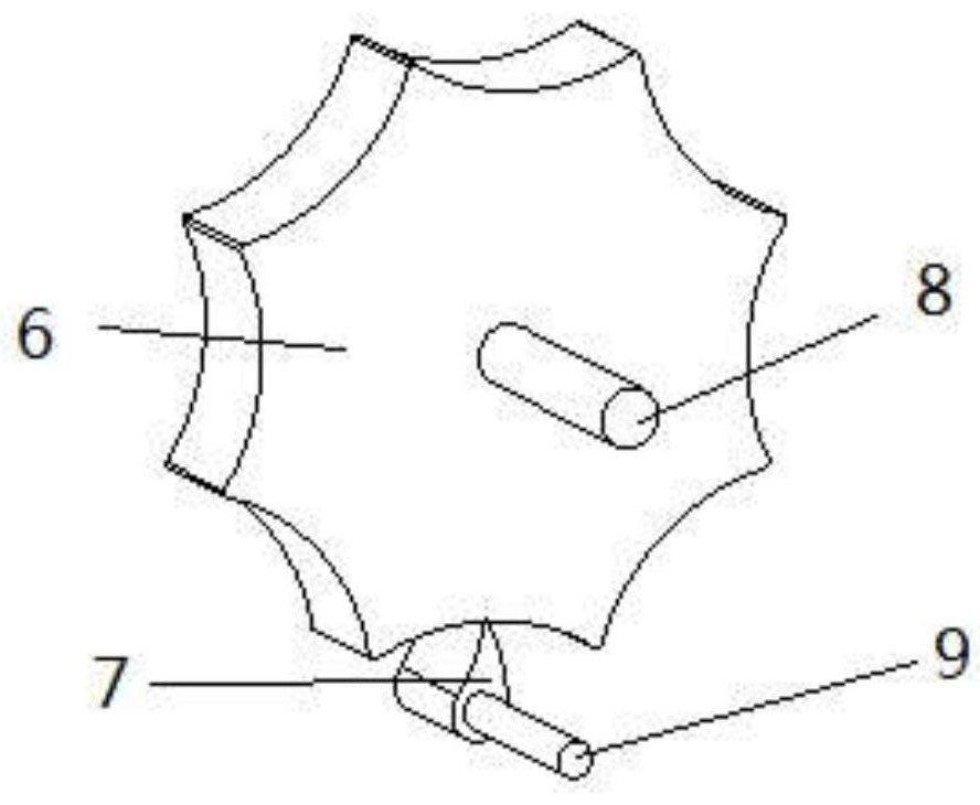
[0019] Such as Figure 1 to Figure 3 Shown is the embodiment of the mutual scraping type cycloid wheel feeding device of the present invention, the feeding device is composed of a cycloid wheel feeding pan 6, a finger 7, a housing 3, a rear end cover 2, a front end cover 4, a feeding port 1. The discharge port 5, the cycloid wheel feeding disc drive shaft 8, the finger drive shaft 9 and other components are assembled. The housing 3 has a hollow chamber structure in the shape of a revolving body, and the cycloid wheel feeding pan 6 is located in the hollow chamber of the housing 3; the top of the housing 3 is provided with a feed port 1, the bottom is provided with a discharge port 5, and the front end cover 4 And the rear cover 2 is located on both sides of the housing 3 . Cycloid wheel feeding tray 6 is installed on the cycloid wheel feeding tray drive shaft 8, and ...


PUM


Abstract

The invention provides a mutually-scraping cycloidal wheel feeding device. The mutually-scraping cycloidal wheel feeding device comprises a cycloidal wheel feeding disc, a shifting claw, a shell, a front end cover, a rear end cover, a feeding port, a discharging port, and a driving shaft of the cycloidal wheel feeding disc and the shifting claw. The theoretical contour of grooves in the cycloidalwheel feeding disc is a short hypocycloid, the number of the grooves is equal to the transmission ratio between the shifting claw and the cycloidal wheel feeding disc, the grooves are evenly distributed in the cycloidal wheel feeding disc in the circumferential direction, and the shifting claw and the cycloidal wheel feeding disc rotate in the same direction. According to the mutually-scraping cycloidal wheel feeding device, a claw point of the shifting claw can scrape the surfaces of the grooves in the cycloidal wheel feeding disc, and a sharp corner of the cycloidal wheel feeding disc can scrape the surface of the shifting claw so that vicious materials can fall off completely, and the problems that when an existing rotary feeding device is used for conveying high-viscosity materials, the materials are likely to adhere to the feeding device, blockage is likely to be caused, the discharging quantity is gradually decreased, and cleaning is troublesome are solved. The claw point of theshifting claw does not make contact with the grooves of the cycloidal wheel feeding disc, so that abrasion is avoided; movable components can rotate flexibly, and the service life is long; and the mutually-scraping cycloidal wheel feeding device can be used as an upgrade product of a closed vicious material feeding device.

Description

technical field [0001] The invention relates to a feeding device, in particular to a rotary feeding device in which the groove of a cycloidal feeding disc and the surface of a claw can scrape each other, and belongs to the technical field of material conveying equipment. Background technique [0002] The key part of the rotary feeding device is the feeding pan with multiple grooves in the circumferential direction. The material in the upper bin falls to fill the grooves by its own weight. With the rotation of the feeding pan, the material is discharged from the lower outlet due to its own weight. Unload. The rotary feeding device is simple in structure, small in size and light in weight, and can evenly transport dry powdery or small granular materials to the receiving device. Where the pressure difference must be small, it has been widely used in tobacco, food, chemical, pharmaceutical and other industries as a feeding device for closed conveying systems. [0003] However,...

Claims


Application Information

Patent Timeline
Patent Type & Authority Patents(China)
IPC IPC(8): B65G29/00
CPCB65G29/00
Inventor 邹旻祝海林
Owner CHANGZHOU UNIV
Why Eureka
Try Eureka