

Waterproof structure of electtrical terminal box
A technology for electrical junction boxes and boxes, which is applied in the direction of electrical components, etc., and can solve problems such as poor waterproof effect
- Summary
- Abstract
- Description
- Claims
- Application Information
AI Technical Summary
Problems solved by technology
Method used
Image

Examples
Embodiment Construction
[0045] Hereinafter, an embodiment of the waterproof structure of an electrical junction box according to the present invention will be described in detail with reference to the drawings.
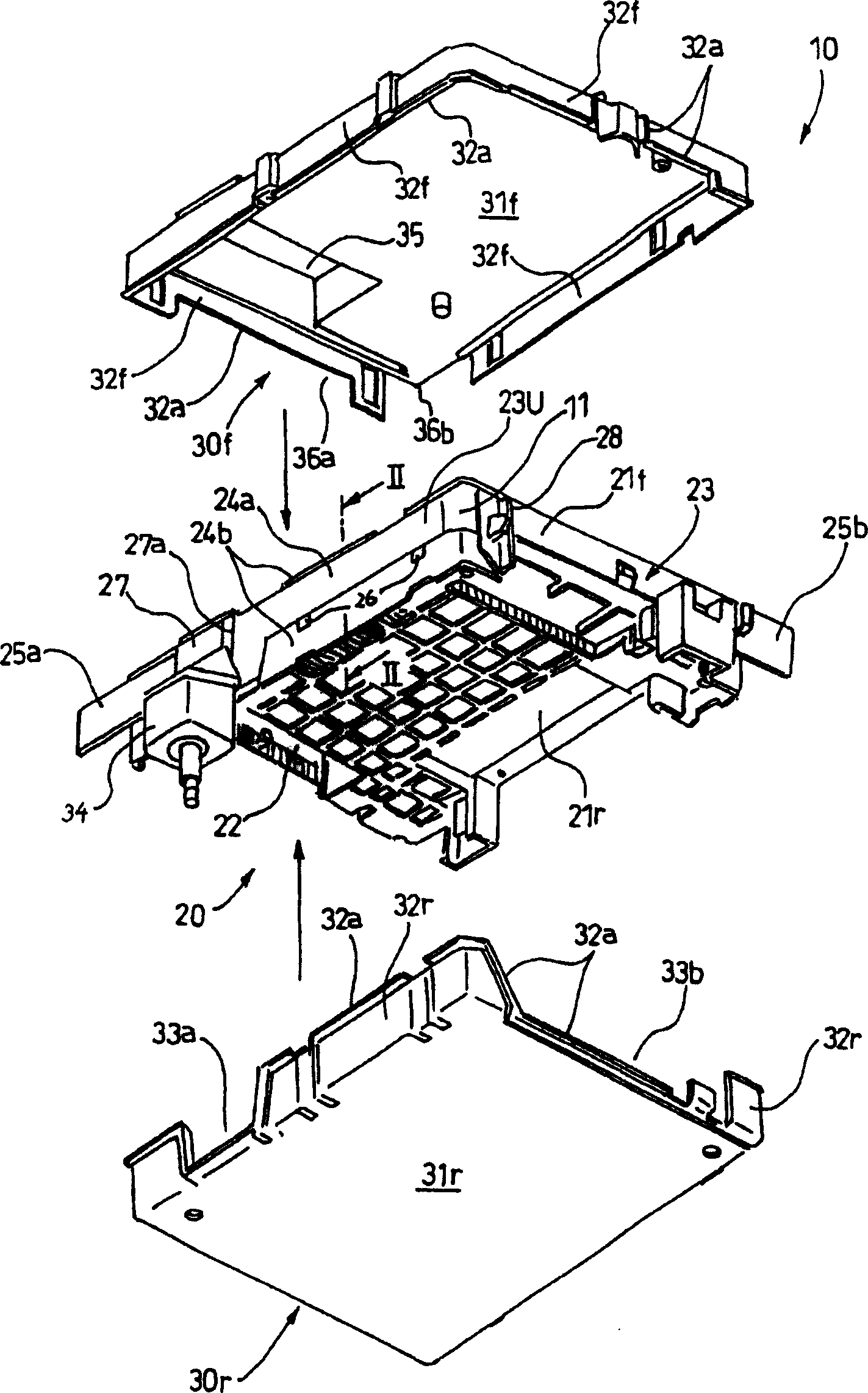
[0046] Such as figure 1 As shown, the electrical junction box 10 related to the present invention has a main body 20 with openings 21f, 21r on both front and rear surfaces, and a pair of cover members 30f, 30f, 30r. The main body 20, the cover members 30f, 30r, etc. are generally made of synthetic resin. This electrical junction box 10 is used, for example, in a state where both openings 21f and 21r of the main body 20 are substantially along a vertical plane.
[0047] The inside of the main body 20 is provided with a receiving and discharging device mounting seat 22 for installing various electrical mounting parts. figure 1The front and rear sides of the middle arrow direction) are provided with body wall portions 23 . In the main body wall 23, at least the upper main body wall 23U in...
PUM
 Abstract
Description
Claims
Application Information