Air conditioning unit drainage structure for railway vehicle

A technology for air-conditioning units and rail vehicles, which is applied to vehicle components, railway vehicle heating/cooling, railway car body components, etc. It can solve problems such as large vehicle space, drainage blockage, and endangering the safety of electrical equipment, and achieves easy cleaning and maintenance. Easy to clean and not easy to be blocked by mud and dust

Active Publication Date: 2011-07-20
GUANGZHOU ZHONGCHE RAIL WAY VEHICLES AIR CONDITIONING EQUIP
View PDF4 Cites 8 Cited by
  • Summary
  • Abstract
  • Description
  • Claims
  • Application Information

AI Technical Summary

Problems solved by technology

[0006] (3) When the vehicle air conditioner unit is in cooling operation, it will produce a large amount of condensed water, which needs to be discharged out of the unit in time, otherwise it will enter the compartment through the air outlet and air duct, affecting passengers and endangering the safety of electrical equipment in the vehicle
[0007] (4) The weight and space of the vehicle air-conditioning unit are strictly limited, and the height of the condensate water receiving tray is limited
Its disadvantages are: (1) The installation of the drain pipe and the water seal need to occupy a large space of the vehicle; (2) When a fault occurs, it is not easy to distinguish whether the responsibility for the poor discharge of air-conditioning condensate is the installation problem of the air-conditioning manufacturer or the vehicle manufacturer
Its disadvantages are: (1) Since the height of the water receiving tray in the unit is very low, and the negative pressure of the drain is very large, it is necessary to set a large sealing compartment and a labyrinth structure at the drain to overcome the negative pressure, so that the The condensed water in the water tray is smoothly discharged to the water collecting tray on the top of the vehicle; (2) There is a great hidden danger in the structure. When the dust in the air passes through the evaporator, it is wetted into mud and enters the water tray, and is driven by the drainage. In the sealed compartment and labyrinth structure, it is easy to deposit in this structure, and eventually lead to drainage blockage; (3) Due to the complex structure of the labyrinth, it is very difficult to clean up after blockage

Method used


Image

  • Air conditioning unit drainage structure for railway vehicle
  • Air conditioning unit drainage structure for railway vehicle
  • Air conditioning unit drainage structure for railway vehicle

Examples


Embodiment Construction

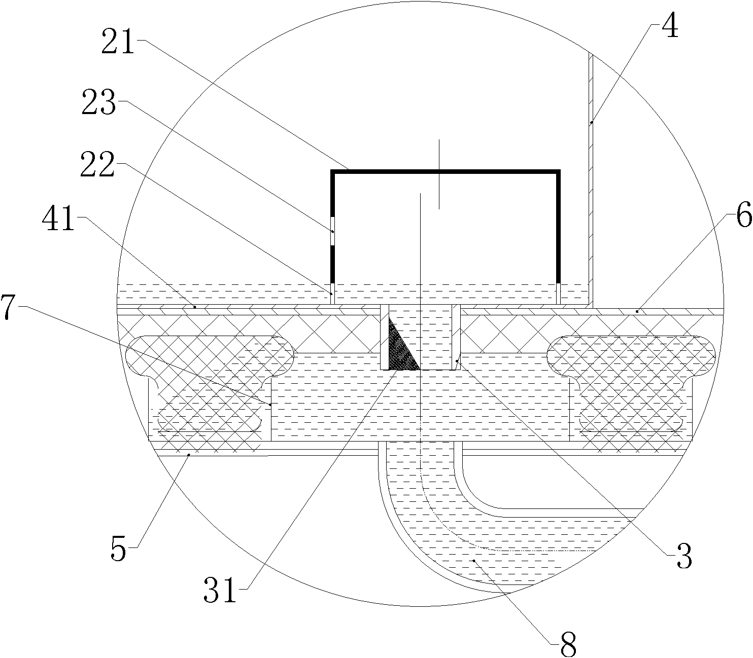
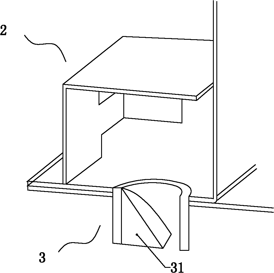
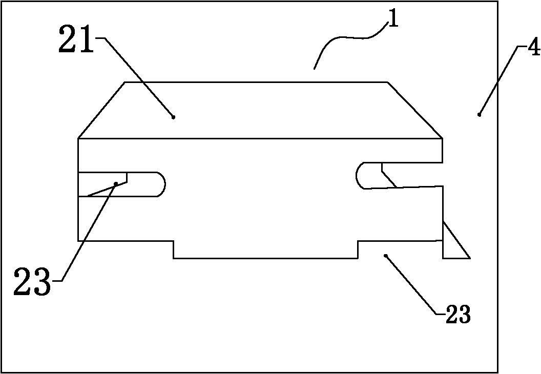
[0026] The drainage structure of the rail vehicle air-conditioning unit according to the present invention adopts the principle of two-stage water seal, and the first-stage water seal structure utilizes the principle of bypass to change the flow direction of the air through the change of the height of condensed water, and finally form a water seal. Thereby overcoming the air negative pressure, the condensed water can smoothly enter the water seal of the variable cross-section drainage pipe of the second stage. The second-stage water seal structure is to use variable cross-section drainage pipes to facilitate the formation of water seals through the principle of decreasing wind speed and dynamic pressure. The water seal structure has a small appearance. In order to facilitate the cleaning and maintenance work, the first-stage water seal structure is detachable, and the water seal structure can be disassembled and assembled by simple bare-hand operation, and the cleaning and main...


PUM


Abstract

The invention discloses an air conditioning unit drainage structure for a railway vehicle. The air conditioning unit drainage structure comprises a drainage disk arranged on the bottom plate of an air conditioning unit, and is characterized by also comprising a first-level water seal structure and a second-level water seal structure; the first-level water seal structure comprises a cover body covered on the drainage disk of the air conditioning unit; the bottom of the cover body is provided with a plurality of notches; the notches and the bottom of the drainage disk form a water inlet passage; a bypass passage is formed in the middle of the cover body; the second-level water seal structure is a variable cross-section drainage pipe; and the opening of the variable cross-section drainage pipe is positioned at the bottom of the drainage disk in the cover body. The required installation space of the air conditioning unit drainage structure is small, the air conditioning unit drainage structure can overcome the negative pressure of the air conditioning unit sufficiently, and has a water seal function; and dust is hardly blocked.

Description

technical field [0001] The invention belongs to the field of air conditioners for rail vehicles, and in particular relates to a drainage structure for an air conditioner unit for rail vehicles. Background technique [0002] At present, in terms of household air conditioners (such as window-type, split-type air-conditioning units) and commercial air-conditioners (such as cabinet-type, ceiling-type, roof-type, and multi-system air-conditioning units), since the air-conditioning units directly supply air to the room, the static pressure of the blower It is very small, and the negative pressure of the corresponding discharge condensate is also small. Moreover, the installation of the air conditioner is static, and there is no need to consider the movement and shaking of the condensed water. Therefore, the height of the baffle plate required for the water receiving pan is very low, and the discharge of the condensed water of the air conditioning unit is quite easy. The location ...

Claims


Application Information

Patent Timeline
Patent Type & Authority Applications(China)
IPC IPC(8): B61D27/00
CPCB60H1/3233
Inventor 杨宇王兴江王亚汉谭治唐松广
Owner GUANGZHOU ZHONGCHE RAIL WAY VEHICLES AIR CONDITIONING EQUIP
Why Eureka
Try Eureka