Pressure regulator assembly for use with a slip joint in a driveshaft assembly

US7052398B2Inactive Publication Date: 2006-05-30DANA AUTOMOTIVE SYST GRP LLC

Image

  • Pressure regulator assembly for use with a slip joint in a driveshaft assembly
  • Pressure regulator assembly for use with a slip joint in a driveshaft assembly

Examples


Embodiment Construction

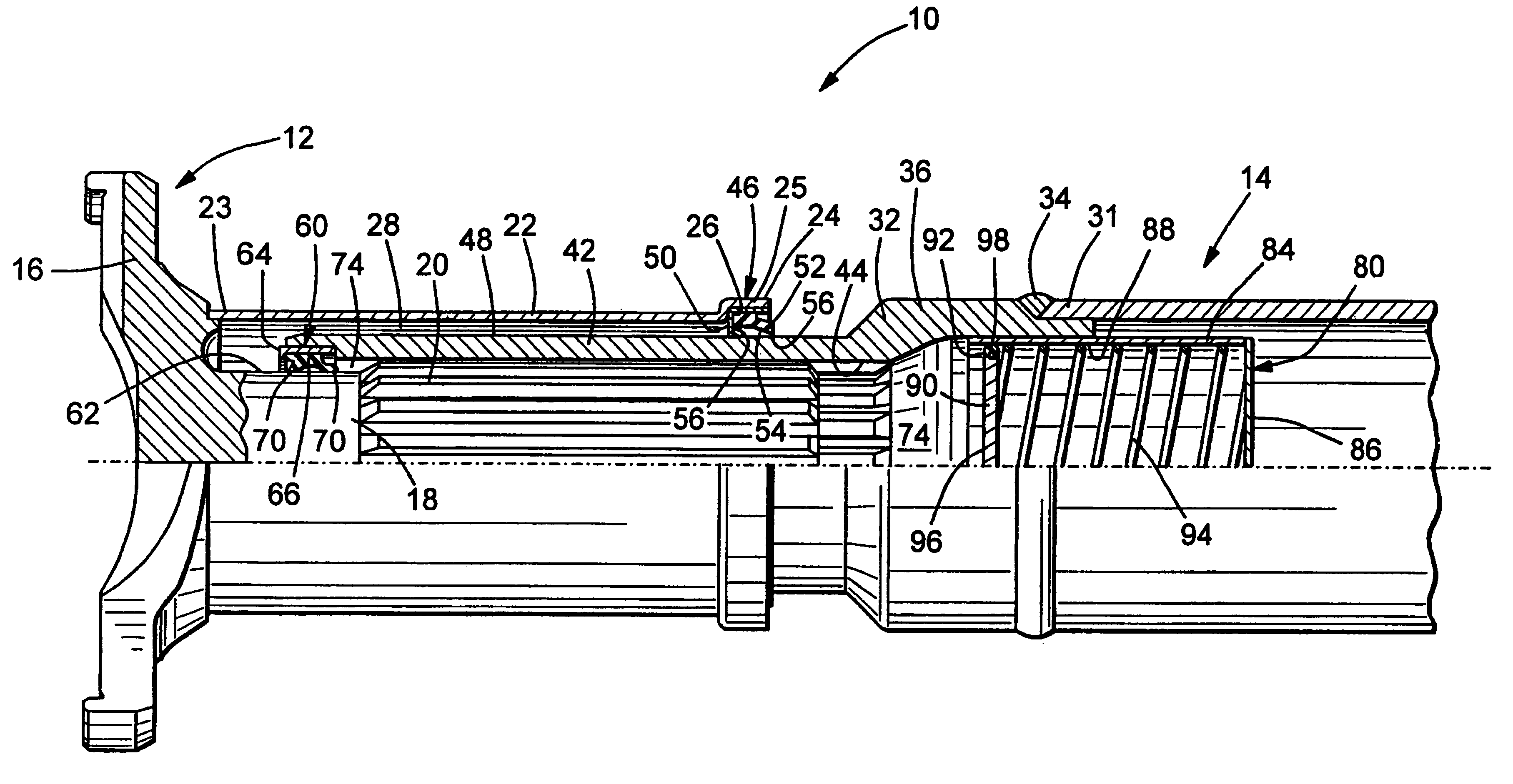
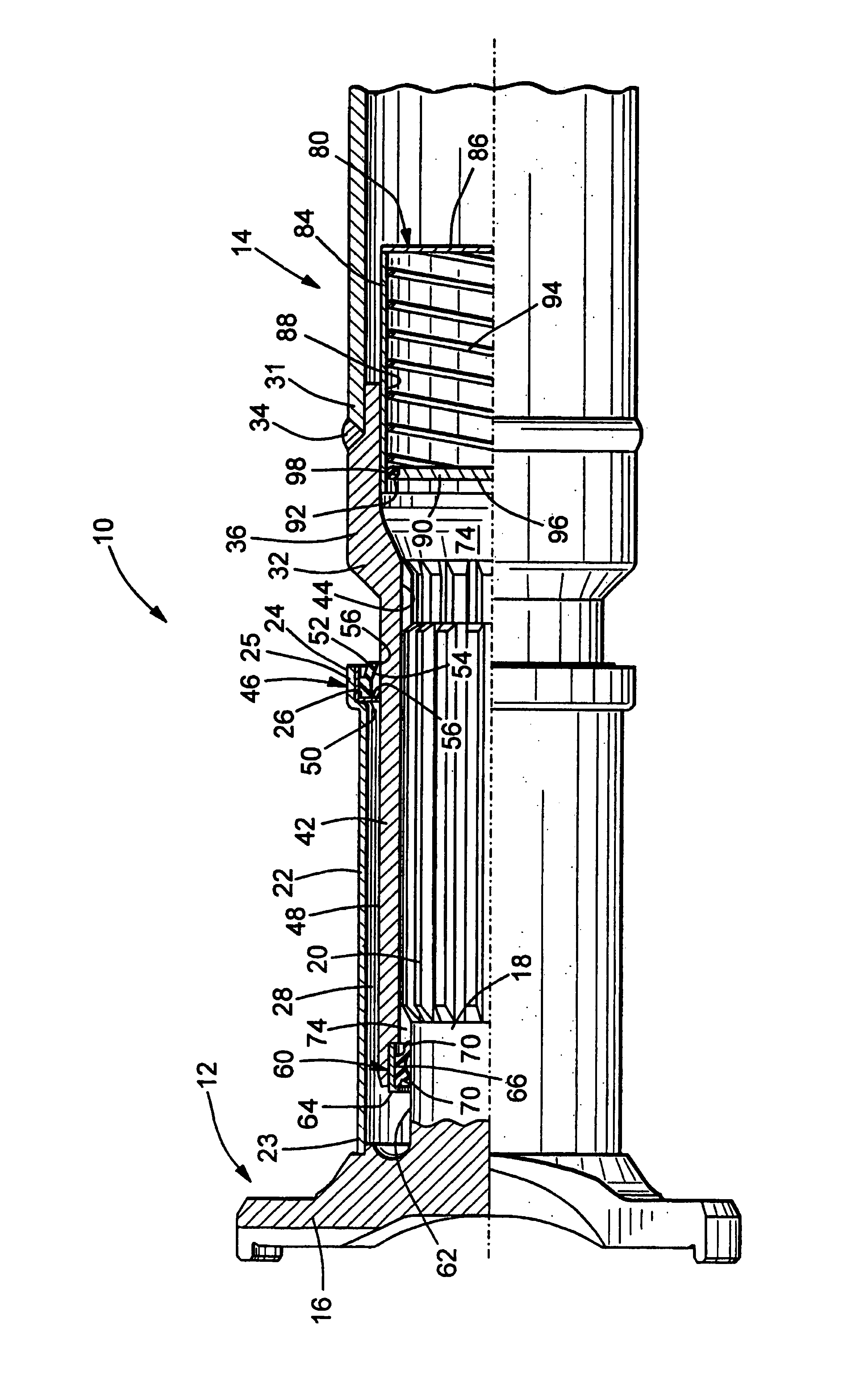
[0010]Referring now to the drawing, there is illustrated a portion of a driveshaft assembly, indicated generally at 10, that can be used, for example, in the drive train system (not shown) of a land vehicle for transmitting rotational force or torque from an engine / transmission assembly to an axle assembly. However, the driveshaft assembly 10 may be used to transmit power from type of any source of power to any type of driven mechanism. Furthermore, although this invention will be described in the context of the illustrated driveshaft assembly 10, it will be appreciated that this invention may be practiced in a variety of applications other that driveshaft assemblies.

[0011]The driveshaft assembly 10 includes a slip yoke, indicated generally at 12, and a driveshaft tube, indicated generally at 14. The slip yoke 12 can be embodied as any end fitting or other member that is adapted to be connected or otherwise coupled with a cooperating component (not shown) to transmit power therebetw...


PUM


Abstract

A slip joint includes a structure that prevents a negative pressure situation from occurring within a sealed lubricant chamber during operation thereof. The slip joint includes a male splined member having a plurality of external splines formed thereon that cooperate with a plurality of internal splines formed on a female splined member. The cooperating splines are disposed within a lubricant chamber defined at one end by a seal assembly and at the other end by a pressure regulator assembly. The pressure regulator assembly includes a housing having an open end that faces toward the lubricant chamber. A pressure plate is disposed within the housing of the pressure regulator assembly and is supported for sliding movement relative thereto. A spring urges the pressure plate toward the open end of the housing and the lubricant chamber. As a result, the pressure plate maintains a positive pressure situation within the lubricant chamber, thereby deterring contaminants from passing through the seal assembly into the region of the cooperating splines.

Description

CROSS REFERENCE TO RELATED APPLICATIONS[0001]This application claims the benefit of U.S. Provisional Application No. 60 / 314,127, filed Aug. 22, 2001, the disclosure of which is incorporated herein by reference.BACKGROUND OF THE INVENTION[0002]This invention relates in general to a slip joint, such as is commonly used in a driveshaft assembly for transmitting rotational force or torque from an engine / transmission to an axle assembly in a vehicle drive train system. In particular, this invention relates to a pressure regulator assembly for use with such a slip joint that compresses a volume of lubricant disposed within a sealed lubricant chamber defined within the slip joint so as to maintain a positive pressure situation within the lubricant chamber and thus deter the entry of contaminants therein.[0003]Drive train systems are widely used for generating power from a source and for transferring such power from the source to a driven mechanism. Frequently, the source generates rotation...

Claims


Application Information

Patent Timeline
30 May 2006
Publication
US7052398B2
IPC
F16N11/04; F16C3/03; F16D3/06
CPC
F16D3/06; F16C3/03; F16D3/848; F16D2300/06
Inventors
ROBB, SCOTT B.