Vibration damper

a damper and vibration technology, applied in the field of vibration dampers, can solve the problems of difficult installation, large radial space, and weak force generated by the restoring spring, and achieve the effect of avoiding extreme stress peaks and simple physical contours

Inactive Publication Date: 2010-06-29
ZF FRIEDRICHSHAFEN AG
View PDF13 Cites 8 Cited by
  • Summary
  • Abstract
  • Description
  • Claims
  • Application Information

AI Technical Summary

Benefits of technology

[0012]According to another advantageous embodiment, the effective cross section of the displacer sleeve in the stop cup increases at least over the length of its stroke. This effect can be achieved, for example, by giving the displacer sleeve a conical contour, across which damping medium can flow into the stop cup during the outward travel of the displacer sleeve.
[0013]To avoid negative pressure from developing in the stop cup, a residual damping cross section is always present between a lateral surface of the displacer sleeve and a wall of the stop cup regardless of the depth to which the displacer sleeve travels into the stop cup.
[0015]The displacer space of the stop cup is bounded radially by the wall of the stop cup and the lateral surface of the piston rod. As a result, the stop cup can have a very simple physical contour.
[0016]To avoid extreme stress peaks in the restoring spring, the displacer sleeve comes to rest axially in the stop cup, and the restoring spring has used up all of its elastic travel.

Problems solved by technology

There are applications, however, in which the forces generated by the restoring springs are too weak, as a result of which each of the restoring springs is formed by two springs arranged one inside the other to form a set.
These sets of springs, however, are difficult to install and occupy a relatively large amount of radial space.
Springs with a progressive spring characteristic are very expensive.

Method used


Image

  • Vibration damper
  • Vibration damper

Examples


Embodiment Construction

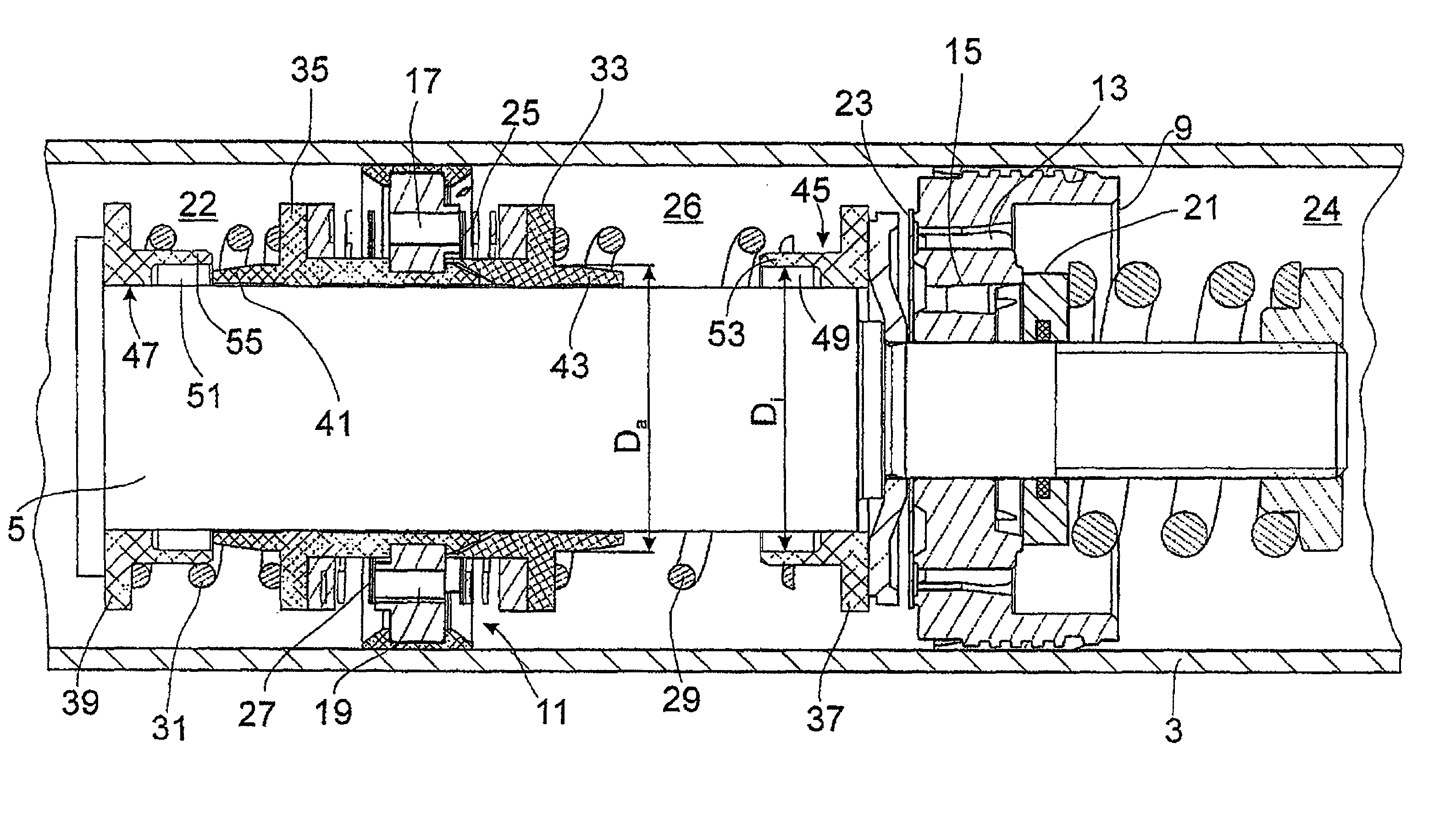
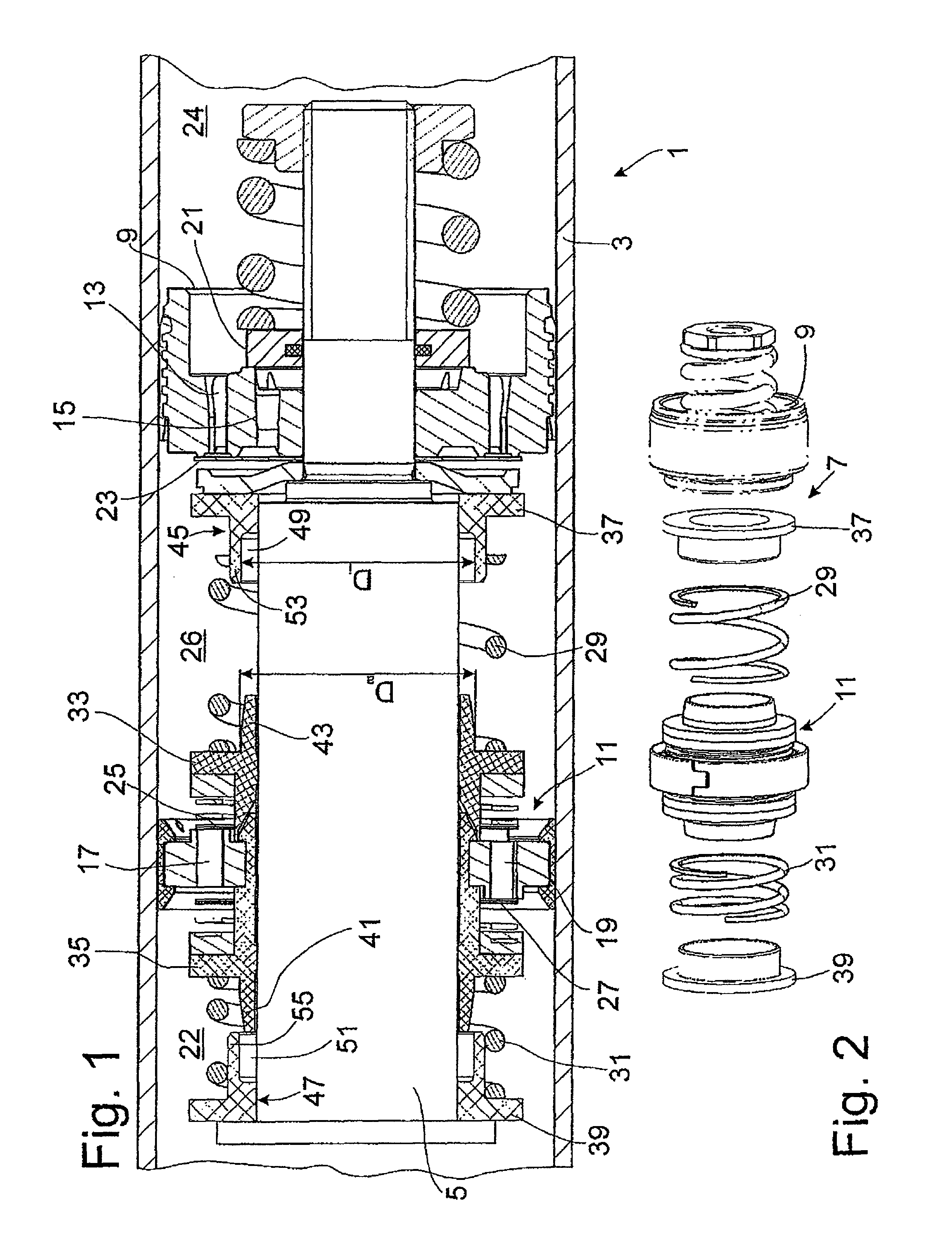
[0021]FIGS. 1 and 2 show part of a vibration damper 1, in the cylinder 3 of which a piston rod 5 is guided with freedom of axial movement. The piston rod 5 cooperates with a piston rod arrangement 7, which has, among other things, a first piston 9, which is mounted permanently on a piston rod pin. In addition, the piston rod arrangement 7 includes a second piston 11, which is supported in such a way that it can move axially on the piston rod within certain limits. Both the first piston 9 and the second piston 11 are designed with flow-through channels 13, 15, 17, 19, each of which is equipped on the outlet side with at least one valve disk 21, 23, 25, 27. The piston arrangement 7 divides the damping medium-filled cylinder 3 into a working space 22 on the side of the piston facing the piston rod, a working space 24 on the side of the piston facing away from the piston rod, and a working space 26 between the two pistons 9, 11.

[0022]The axially movable piston 11 is pretensioned on each...


PUM


Abstract

Vibration damper comprising a cylinder in which a piston rod is guided with freedom of axial movement, where the piston rod cooperates with a piston arrangement comprising a first, stationary piston and at least one additional piston, which is supported on the piston rod with freedom of axial movement against the elastic force of at least one restoring spring, where the cylinder is divided by the stationary piston and by the minimum of one axially movable piston into a working space on the side of the piston facing the piston rod, a working space on the side of the piston facing away from the piston rod, and a working space between the two pistons, where valve-equipped through-openings control a connection between the working spaces, and where the axial movement of the minimum of one axially movable piston is limited by a hydraulic pressure stop.

Description

BACKGROUND OF THE INVENTION[0001]1. Field of the Invention[0002]The invention pertains to a vibration damper of the type having a piston rod guided with freedom of axial movement in a cylinder; a first piston fixed to the piston rod so that the first piston is stationary with respect to the piston rod, the first piston bounding a first working space facing away from the piston rod; and a second piston mounted on the piston rod with freedom to move axially with respect to the first piston against the force of at least one restoring spring, the second piston bounding a second working space facing the piston rod and an intermediate working space between the pistons; and at least two openings in each piston connecting the working spaces, the openings being equipped with non-return valves.[0003]2. Description of the Related Art[0004]A vibration damper with a cylinder in which a piston rod is guided with freedom of axial movement, where a first piston is mounted in a stationary manner on ...

Claims


Application Information

Patent Timeline
Patent Type & Authority Patents(United States)
IPC IPC(8): F16F9/56
CPCF16F9/5126F16F9/49F16F9/32F16F15/02
Inventor KRAWCZYK, ANTON
Owner ZF FRIEDRICHSHAFEN AG
Why Eureka
Try Eureka