A mobile medium wave cage antenna

A cage-shaped antenna, mobile technology, applied in the direction of antenna support/installation device, radiation element structure, etc., can solve the problems of affecting the normal navigation of the route, the effective height of the antenna is small, and the time-consuming repair of the antenna, etc., to achieve the effective cross-section Large, small wind resistance, small impact effect

Active Publication Date: 2017-02-01
泰兴市东盛通讯器材有限公司
View PDF5 Cites 0 Cited by
  • Summary
  • Abstract
  • Description
  • Claims
  • Application Information

AI Technical Summary

Problems solved by technology

The T-shaped antenna is commonly used as the transmitting antenna in the existing medium-wave navigation. It is formed by adding a top load composed of a horizontal wire on the top of the vertical part of the wire. The antenna uses two towers to support the two ends of the horizontal part of the antenna respectively. The effective height of the antenna is Small, small radiation resistance, low efficiency, narrow passband, small directivity coefficient, and poor wind resistance. When the navigation antenna is damaged due to sudden accidents, it takes a lot of time to repair the antenna, which affects the normal navigation of the route

Method used


Image

  • A mobile medium wave cage antenna
  • A mobile medium wave cage antenna

Examples


Embodiment Construction

[0016] The present invention will be further described below in conjunction with drawings and embodiments.

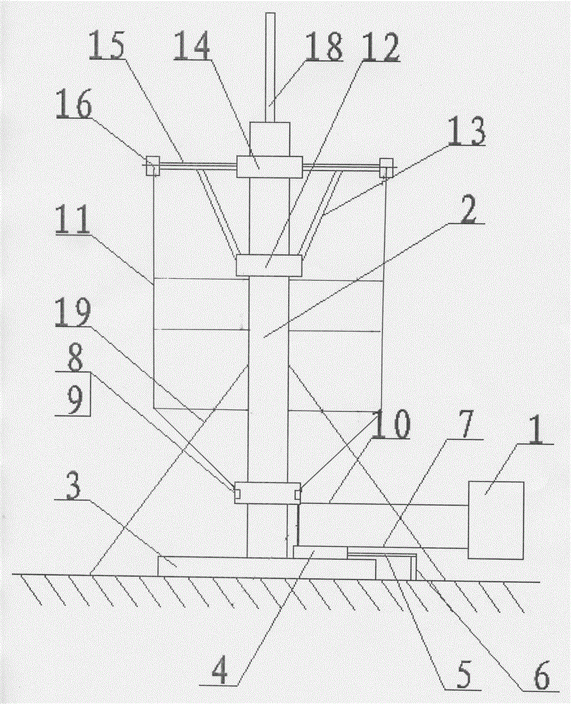
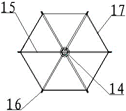
[0017] figure 1 , 2 As shown, a mobile medium-wave cage antenna includes an antenna mast 2, a chassis 3, a ground frame 4, a ground wire 5, a ground nail 6, a ground wire 7, a feed clip 8, a feed hole 9, and an output cable 10 , radiation cable 11, lower support clip 12, support arm 13, upper support clip 14, vibrator arm 15, antenna head junction box 16, amplitude cable 17, lightning rod 18 and stay cord 19. The top of the antenna mast 2 is provided with upper and lower support clips 14, 12 from top to bottom. The six vibrator arms 15 evenly surround the antenna mast 2 and are vertically hinged on the upper support clip 14. The six vibrator arms 15 are respectively supported and connected by six support arms 13. On the lower support clip 12 of the antenna mast, the support arm 13, the vibrator arm 15 and the lower support clip 12 are articulated in a state where the ...


PUM


Abstract

The invention relates to a movable medium-wave cage antenna. An antenna mast is tensioned by pull ropes to be erected on the ground, a bottom plate and a grounding grid rack at the bottom of the antenna mast are grounded, and the top of the antenna mast is connected with an antenna oscillator through folding and unfolding of an umbrella framework. The cage antenna is convenient and quick to install and use and suitable for being used in emergencies. The antenna oscillator is of a hexagonal structure, and is large in effective section, wide in frequency band and high in efficiency. The antenna oscillator, radiating cables and feeder clamps form a centrosymmetric cage shape of a vertical structure, the height of the antenna is effectively reduced, the bandwidth and the windward area of the antenna are increased, wind resistance is little, stability is high, and influences on a directional diagram of the antenna are small.

Description

technical field [0001] The invention relates to an antenna, in particular to a mobile medium-wave antenna with a cage structure. Background technique [0002] The traditional medium-wave navigation antenna is fixedly installed on the extension line of the runway to guide the aircraft to return to the route or fly along the route at the navigation point in the airport area. The T-shaped antenna is commonly used as the transmitting antenna in the existing medium-wave navigation. It is formed by adding a top load composed of a horizontal wire on the top of the vertical part of the wire. The antenna uses two towers to support the two ends of the horizontal part of the antenna respectively. The effective height of the antenna is Small, small radiation resistance, low efficiency, narrow passband, small directivity coefficient, and poor wind resistance. When the navigation antenna is damaged due to sudden accidents, it takes a lot of time to repair the antenna, which affects the no...

Claims


Application Information

Patent Timeline
Patent Type & Authority Patents(China)
IPC IPC(8): H01Q1/12H01Q1/36
Inventor 王鸿来王骋王一夫王丽陆九文杨俊忠
Owner 泰兴市东盛通讯器材有限公司
Why Eureka
Try Eureka