Multi-way valve for tractor hydraulic lifter

A technology for hydraulic lifters and tractors, applied in the field of multi-way valves, can solve problems such as inconvenient operation, achieve the effects of convenient operation, improve stability and safety, and prevent uncontrolled self-dropping

Pending Publication Date: 2018-12-14
JINGSHAN HYDRAULIC ELEMENT LUOYANG CITY
View PDF1 Cites 7 Cited by
  • Summary
  • Abstract
  • Description
  • Claims
  • Application Information

AI Technical Summary

Problems solved by technology

[0003] The Chinese patent No. 201210163927.8 records a two-position multi-way valve and a tractor hydraulic lifting system. The non-operating end of the valve stem in the two-position multi-way valve described in the document is equipped with an automatic reset device, but the automatic reset device After the handle is released and the external force is removed, the valve stem will automatically return to the neutral position under the action of the return spring. It is impossible to fix the valve stem in the lifting state when lifting the agricultural implement, or manually fix the valve stem in the lifting state. Need to manually pull the handle to reset the valve stem, the operation is more inconvenient

Method used


Image

  • Multi-way valve for tractor hydraulic lifter
  • Multi-way valve for tractor hydraulic lifter

Examples


Embodiment Construction

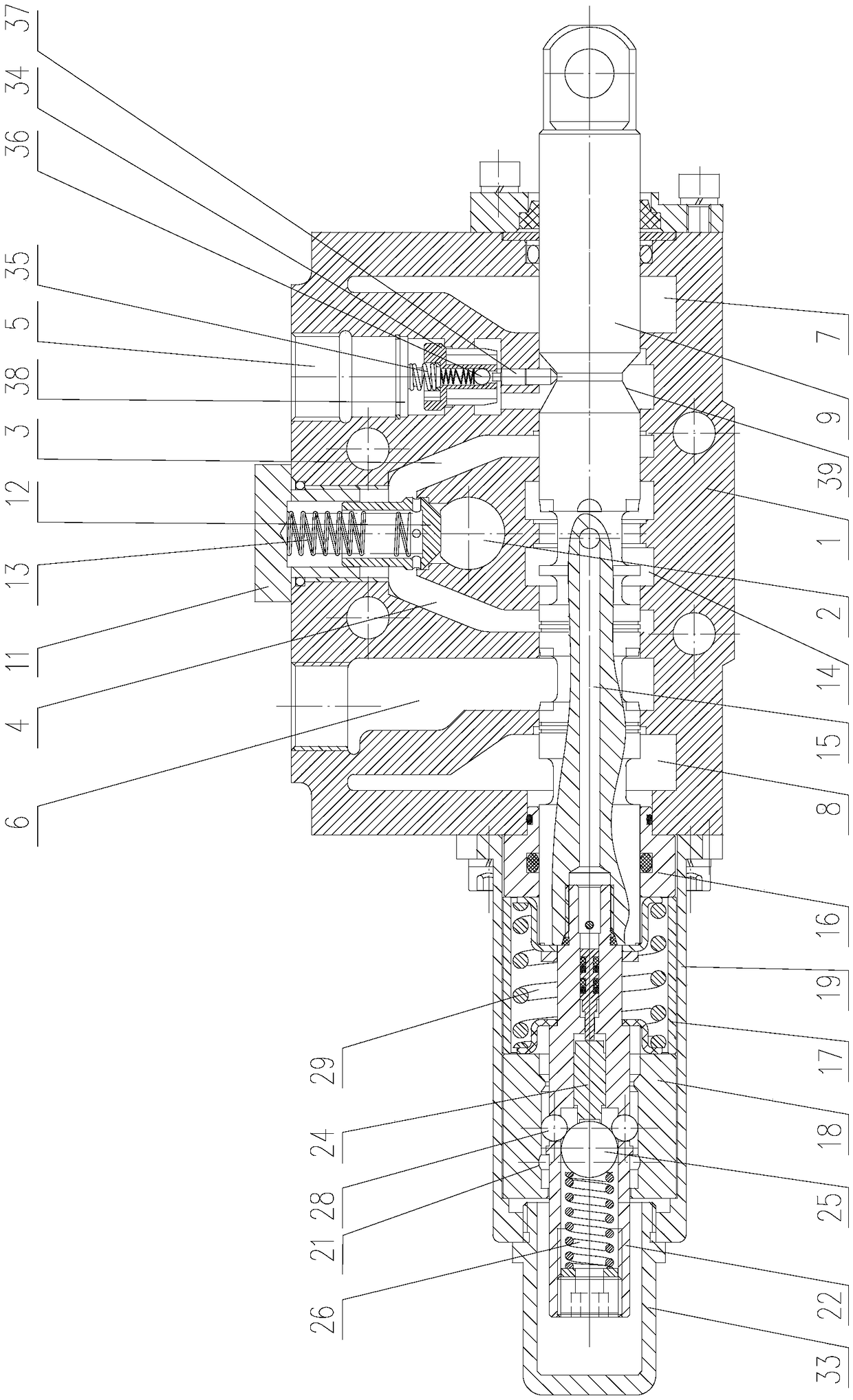
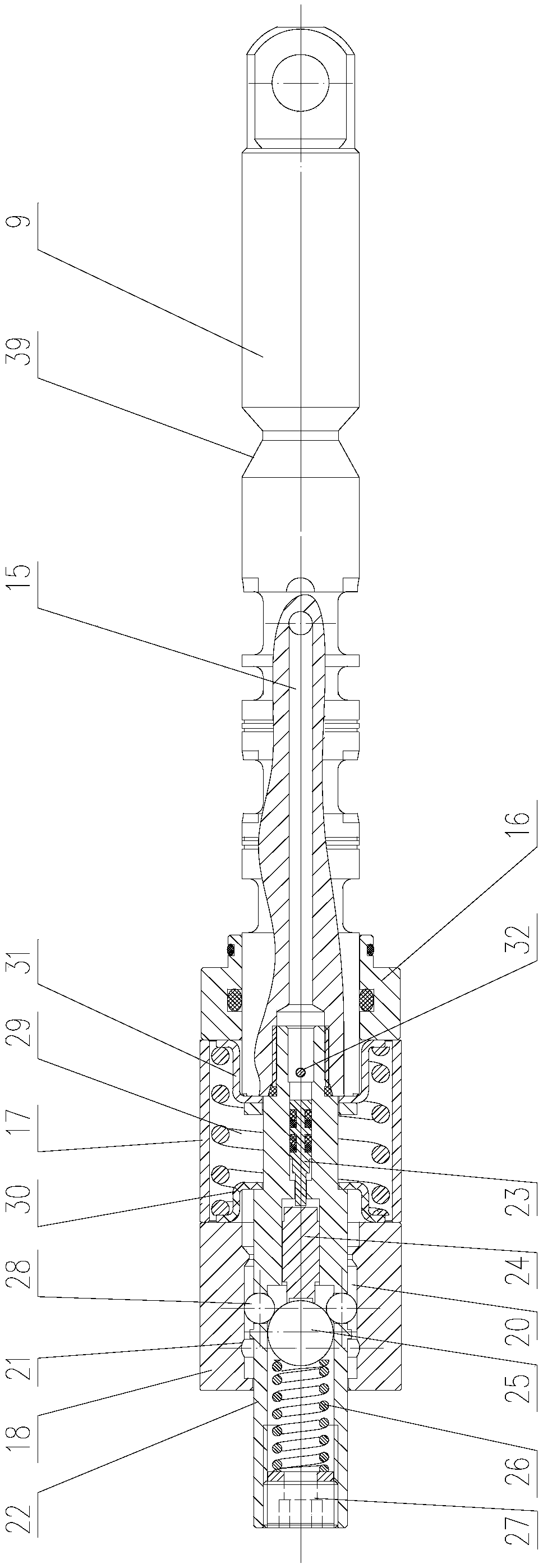
[0017] Such as figure 1 and figure 2 As shown, the multi-way valve for tractor hydraulic lifter of the present invention comprises valve body 1, and valve body 1 is provided with oil inlet chamber 2, oil passage A 3, oil passage B 4, oil outlet chamber A 5, oil outlet Chamber B 6, oil return chamber A 7, oil return chamber B 8 and valve stem 9, valve stem 9 is airtight and slidingly connected with valve body 1, installed at the intersection of oil inlet chamber 2, oil passage A 3 and oil passage B 4 There is a one-way valve, and the one-way valve includes a one-way valve seat 11, a conical valve body 12 and a one-way valve spring 13, and the one-way valve spring 13 is assembled in the valve body 1 through the one-way valve seat 11, and the one-way valve The valve seat 11 and the valve body 1 are sealed with a sealing ring; the valve stem 9 is equipped with oil passage A 3, oil passage B 4, oil outlet chamber A 5, oil outlet chamber B 6, oil return chamber A 7 and The ring g...


PUM


Abstract

The invention discloses a multi-way valve for a tractor hydraulic lifter. The multi-way valve for the tractor hydraulic lifter comprises a valve body, wherein an oil inlet cavity, an oil channel A, an oil channel B, an oil outlet cavity A, an oil outlet cavity B, an oil return cavity A, an oil return cavity B and a valve rod are arranged in the valve body, and the valve rod is in hermetic and sliding connection with the valve body; the valve rod is provided with annular grooves corresponding to the oil channel A, the oil channel B, the oil outlet cavity A, the oil outlet cavity B, the oil return cavity A and the oil return cavity B, an operating end of the valve rod is connected with a handle, and a pressurization cavity is further formed in the valve body; when the valve rod slides to the direction of the oil outlet cavity B, the oil channel A communicates with the oil outlet cavity A, and the oil channel B communicates with the pressurization cavity; a hydraulic reset hole is formedin the interior of the valve rod in the axial direction, an inlet end of the hydraulic reset hole communicates with the pressurization cavity, an outlet end of the hydraulic reset hole faces a non-operating end of the valve rod, and a reset device is arranged at the non-operating end of the valve rod. According to the multi-way valve for the tractor hydraulic lifter, automatic reset function is realized in the descending state and the lifting state of an agricultural implement, the valve rod does not need to be manually reset manually, and the operation is convenient.

Description

technical field [0001] The invention belongs to the field of agricultural machinery and relates to a multi-way valve used for a tractor hydraulic lifter. Background technique [0002] The agricultural implements towed behind the tractor are required to be lowered or lifted, and this action is realized by the hydraulic lifter on the tractor. The hydraulic lifter consists of an outer lift arm and an inner lift arm connected together by the lift arm shaft, a piston rod hinged on the inner lift arm, the piston rod is connected to the piston of the hydraulic cylinder, and a multi-way valve is installed on one side of the hydraulic cylinder , the two oil outlets on the multi-way valve are respectively connected to the lifting oil inlet and the lowering oil inlet on the hydraulic cylinder, the oil inlet on the multi-way valve is connected to the hydraulic pump through a pipeline, and the oil return on the multi-way valve The port is connected to the oil storage tank. [0003] The...

Claims


Application Information

Patent Timeline
Patent Type & Authority Applications(China)
IPC IPC(8): F15B13/04
CPCF15B13/0402F15B2013/0412
Inventor 晋玉国郭会民郭兆贵钟红亮钟继坤刘涛
Owner JINGSHAN HYDRAULIC ELEMENT LUOYANG CITY
Why Eureka
Try Eureka