A detection method for an inertial rotor

A detection method and rotor technology, applied in the detection field, can solve problems such as easy pressure deviation, difficult measurement, and difficult clamping

Active Publication Date: 2020-10-20
XIAN FLIGHT SELF CONTROL INST OF AVIC
View PDF20 Cites 0 Cited by
  • Summary
  • Abstract
  • Description
  • Claims
  • Application Information

AI Technical Summary

Problems solved by technology

The reasons are: 1. It is not easy to measure. The element to be measured is a small arc surface, the size of which is less than 1 / 3 of the circumference. For clamping, there is no effective clamping support surface and effective pressing and fixing surface. The only surface that can be used is a thin ring-shaped facet, which is easy to be biased when clamping and pressing
At present, a three-coordinate measuring machine is used for measurement and a six-jaw chuck is used for clamping. The disadvantages are low clamping efficiency and low clamping accuracy. The data output by this measurement method has poor repeatability and poor traceability.

Method used


Image

  • A detection method for an inertial rotor
  • A detection method for an inertial rotor
  • A detection method for an inertial rotor

Examples


Embodiment Construction

[0014] Below in conjunction with accompanying drawing, the present invention is further described:

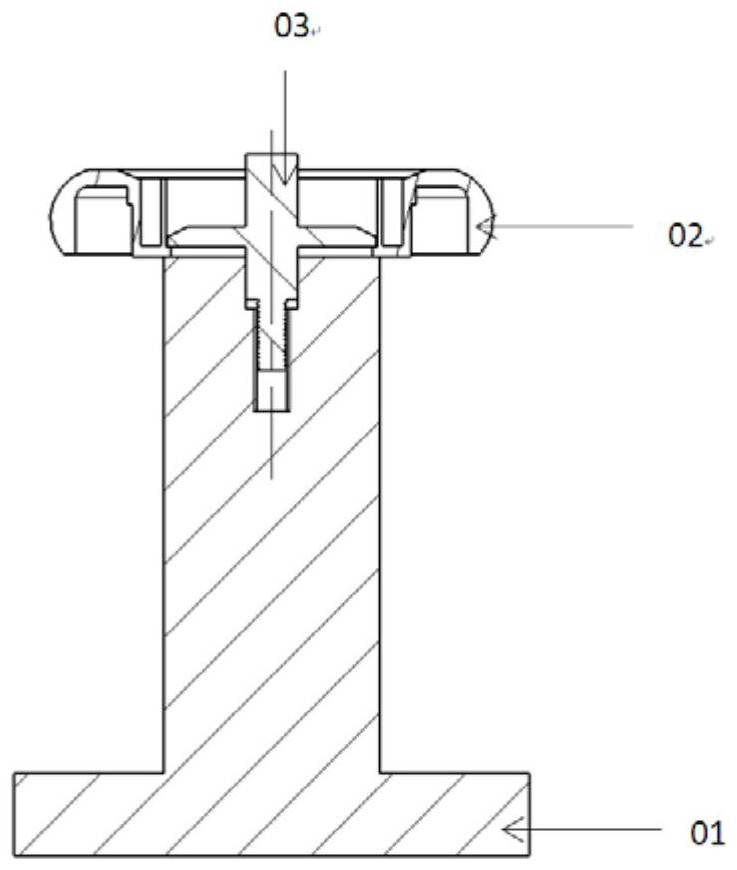
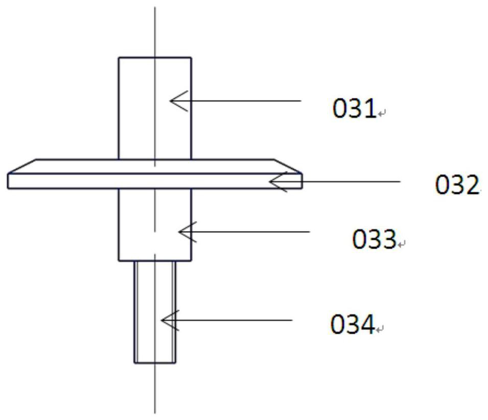
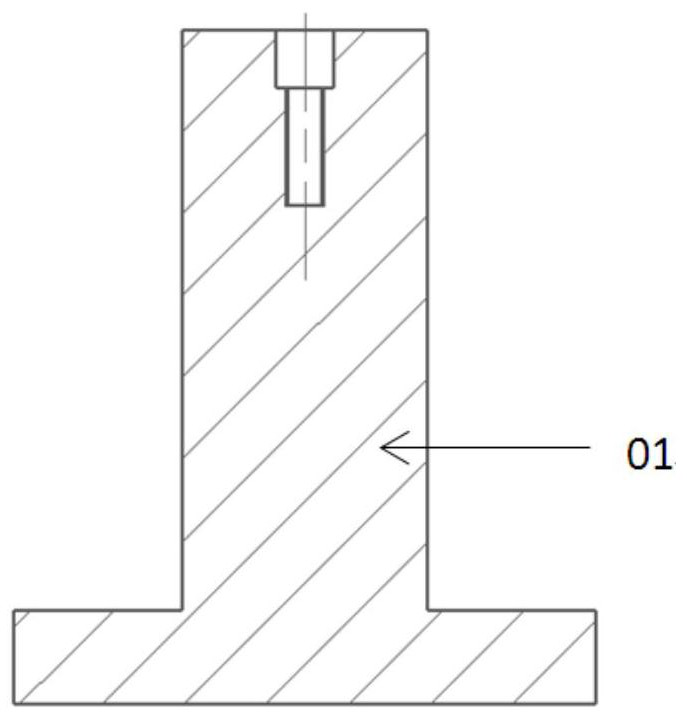
[0015] A method for detecting an inertial rotor, which is characterized in that the lower surface of the inertial rotor is placed in a self-made inertial rotor detection tool, the large hole in the center step hole of the inertial rotor is centered, and the end face of the small hole in the center step hole of the inertial rotor is pressed tightly to increase the The effective measurement range of the center step hole and the large hole, the pressing force is balanced, the measuring needle of the three-coordinate measuring machine is moved to any position in the center step hole of the inertial rotor except the upper and lower edges, and the operating lever of the three-seat meter measuring machine is manually operated. Collect points on the circumference of any position except the upper and lower edges on the big hole in the center step hole of the inertial rotor, read the valu...


PUM


Abstract

The invention belongs to a detection technology, and particularly relates to a detection method of an inertial rotor. According to the detection method, the structure of the inertial rotor is utilizedeffectively, a local area of the detected surface is selected as orientation, and point picking-up touch of a measuring machine is reasonably avoided, large holes of center step holes of the inertialrotor are centered, the end faces of small holes of the center step holes of the inertial rotor are pressed, thus the structure of the inertial rotor is utilized effectively, and the effective measuring range of the large holes of the center step holes is also enlarged; through the detection method, the inertial rotor is clamped and measured, so that measurement element point location picking-upof the small arc surface of the inertial rotor is accurate, the efficiency is high, repeatability is good, traceability is achieved, the clamping error is small, and the accuracy of point picking-up of the measuring machine is ensured.

Description

technical field [0001] The invention belongs to detection technology, and in particular relates to a detection method of an inertial rotor. Background technique [0002] The inertia rotor is an important part of the navigation power tuning gyro. It has a special structure, high precision requirements, and difficult measurement. Different measuring equipment and different inspectors often have different measurement data, which brings some confusion to the measurement. The reasons are: 1. It is not easy to measure. The element to be measured is a small arc surface, the size of which is less than 1 / 3 of the circumference. For clamping, there is no effective clamping support surface and effective pressing and fixing surface. The only surface that can be used is a thin ring-shaped facet, which is easy to be biased when clamping and pressing. At present, a three-coordinate measuring machine is used for measurement and a six-jaw chuck is used for clamping. The disadvantages are lo...

Claims


Application Information

Patent Timeline
Patent Type & Authority Patents(China)
IPC IPC(8): G01B21/00B25B11/00
CPCB25B11/00G01B21/00
Inventor 刘阳森王敏灵
Owner XIAN FLIGHT SELF CONTROL INST OF AVIC
Why Eureka
Try Eureka