Inertial rotor detection tooling

A technology for testing tooling and rotors, applied in the field of testing, can solve problems such as not easy measurement, not easy to clamp, no clamping support surface to press the fixed surface, etc., to increase the effective measurement range, ensure accuracy, and clamp Small error effect

Inactive Publication Date: 2019-01-04
XIAN FLIGHT SELF CONTROL INST OF AVIC
View PDF20 Cites 0 Cited by
  • Summary
  • Abstract
  • Description
  • Claims
  • Application Information

AI Technical Summary

Problems solved by technology

The reasons are: 1. It is not easy to measure. The element to be measured is a small arc surface, the size of which is less than 1 / 3 of the circumference. For clamping, there is no effective clamping support surface and effective pressing and fixing surface. The only surface that can be used is a thin ring-shaped facet, which is easy to be biased when clamping and pressing
At present, a three-coordinate measuring machine is used for measurement, and a six-jaw chuck is used for clamping. The disadvantages are that the clamping efficiency is low, the data output by this measurement method has poor repeatability, and the data traceability is poor.

Method used


Image

  • Inertial rotor detection tooling
  • Inertial rotor detection tooling
  • Inertial rotor detection tooling

Examples


Embodiment Construction

[0013] Below in conjunction with accompanying drawing, the present invention is further described:

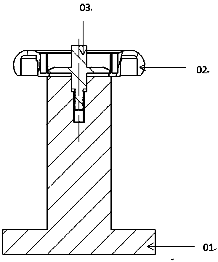
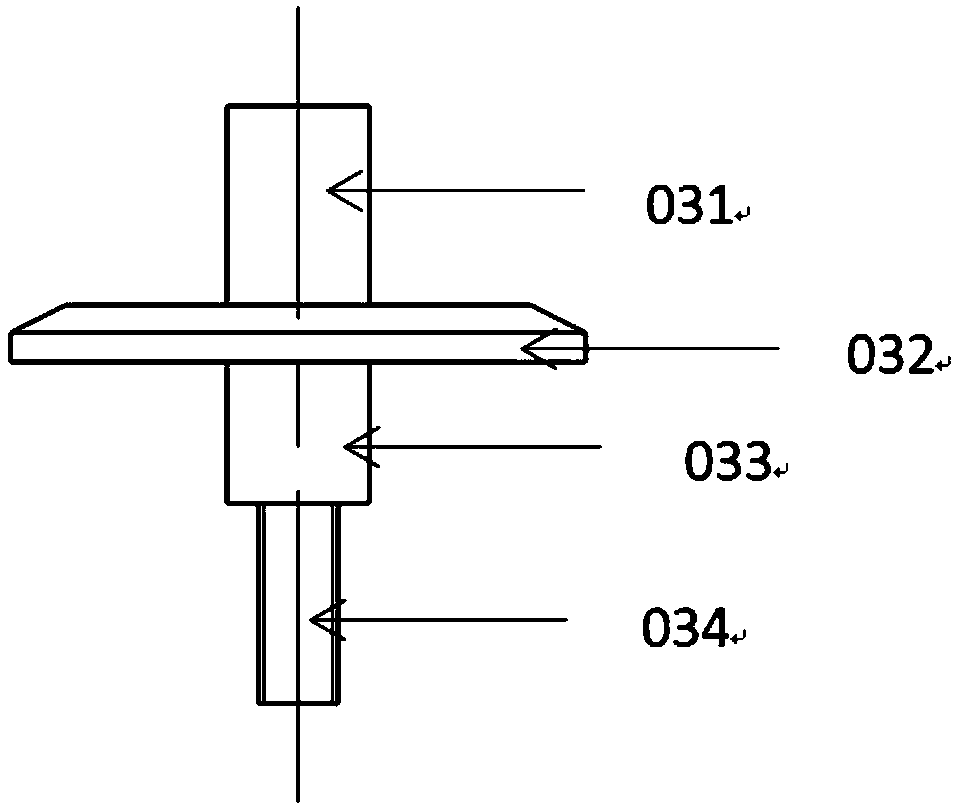
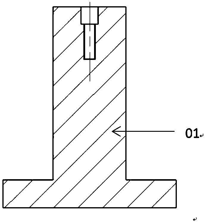
[0014] like Figure 1 to Figure 4 As shown, an inertial rotor detection tool is characterized in that it includes a main body 01 of the tooling and a compression cap 03; the main body 01 is a stepped cylinder, the lower end is a chassis, and the center of the upper end is provided with a second-level stepped hole, and the second-level stepped hole and The main body 01 is coaxial with the step cylinder, the small diameter part of the step hole is provided with threads, and the upper end surface is parallel to the lower chassis plane; the compression cap 03 includes the knob rod 031, the disc 032, the precision guide column 033, the threaded rod 034, and the compression cap 03 is installed in the upper end step hole of the main body 01, the threaded rod 034 is threaded with the small diameter part of the step hole, the bottom surface of the disc 032 is attached to the upper surfa...


PUM


Abstract

The invention belongs to the detection technology and especially relates to an inertial rotor detection tooling. The tooling comprises a tooling main body (01) and a compaction cap (03). In the invention, through effectively using an inertial rotor structure, the local area of a detected surface is selected as an orientation, and measuring machine samping point touch is reasonably avoided. The large hole of the center step hole of an inertial rotor is used to carry out centering, and the small hole end surface of the center step hole of the inertial rotor is compressed. The inertial rotor structure is fully used and the effective measuring range of the large hole of the center step hole is increased. The inertial rotor is clamped, inertial rotor small arc surface measurement element pointpositions can be picked accurately, efficiency is high, repeatability is good, the tooling is traceable, a clamping error is small, and the precision of measuring machine sampling points is guaranteed.

Description

technical field [0001] The invention belongs to detection technology, and in particular relates to an inertial rotor detection tool. Background technique [0002] The inertia rotor is an important part of the navigation power tuning gyro. It has a special structure, high precision requirements, and difficult measurement. Different measuring equipment and different inspectors often have different measurement data, which brings some confusion to the measurement. The reasons are: 1. It is not easy to measure. The element to be measured is a small arc surface, the size of which is less than 1 / 3 of the circumference. For clamping, there is no effective clamping support surface and effective pressing and fixing surface. The only surface that can be used is a thin ring-shaped facet, which is easy to be biased when clamping and pressing. At present, a three-coordinate measuring machine is used for measurement and a six-jaw chuck is used for clamping. The disadvantages are low clamp...

Claims


Application Information

Patent Timeline
IPC IPC(8): G01B21/04
CPCG01B21/047
Inventor 刘阳森王敏灵毛瑞
Owner XIAN FLIGHT SELF CONTROL INST OF AVIC
Why Eureka
Try Eureka