Pressure compensation chamber

Pending Publication Date: 2020-11-05
FAS MEDIC SA
View PDF0 Cites 0 Cited by
  • Summary
  • Abstract
  • Description
  • Claims
  • Application Information

AI Technical Summary

Benefits of technology

This patent describes a device that can balance fluid pressure in a case to prevent leaks or sensor failure. This is achieved through a pressure compensation chamber that reduces the difference between the fluid pressure inside the case and the surrounding atmosphere. This design simplifies the structure of the device and allows for the use of lighter components, which is particularly beneficial for compact devices like miniature MFCs. The device can also have multiple sensing heads to increase the range of flow rates it can accurately measure.

Problems solved by technology

However, fluid sensor casings have a limited capacity to resist internal pressure.
This means that any pressure peak of over 3 bar could cause the sensor to fail and ultimately would result in fluid leakage.
However, such fluid sensors tend to be larger, heavier, and more expensive and, therefore, not appropriate for all applications, for example miniature MFCs.
Increased robustness of the fluid sensor can also lead to an increase in manufacturing complexity and cost.

Method used


Image

  • Pressure compensation chamber
  • Pressure compensation chamber
  • Pressure compensation chamber

Examples


first embodiment

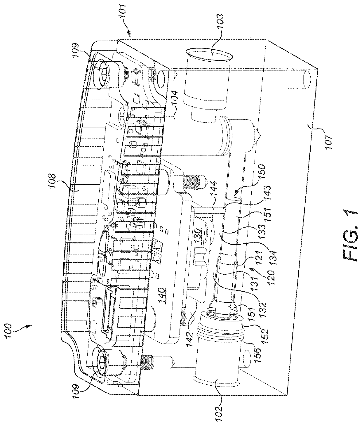
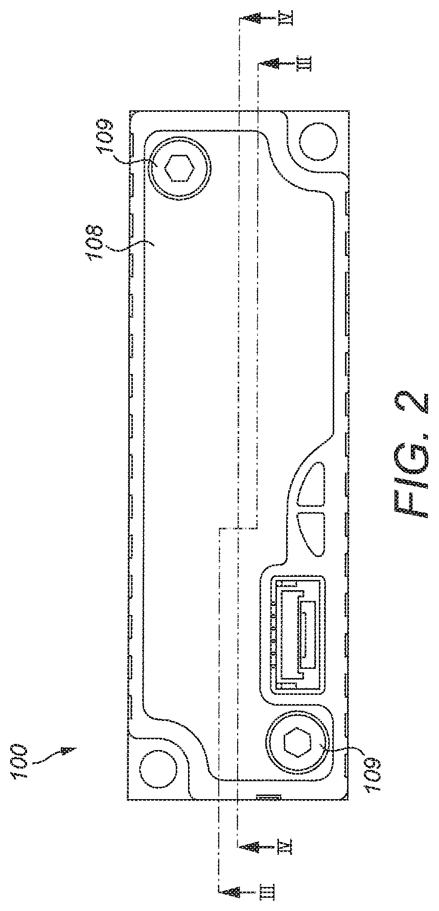
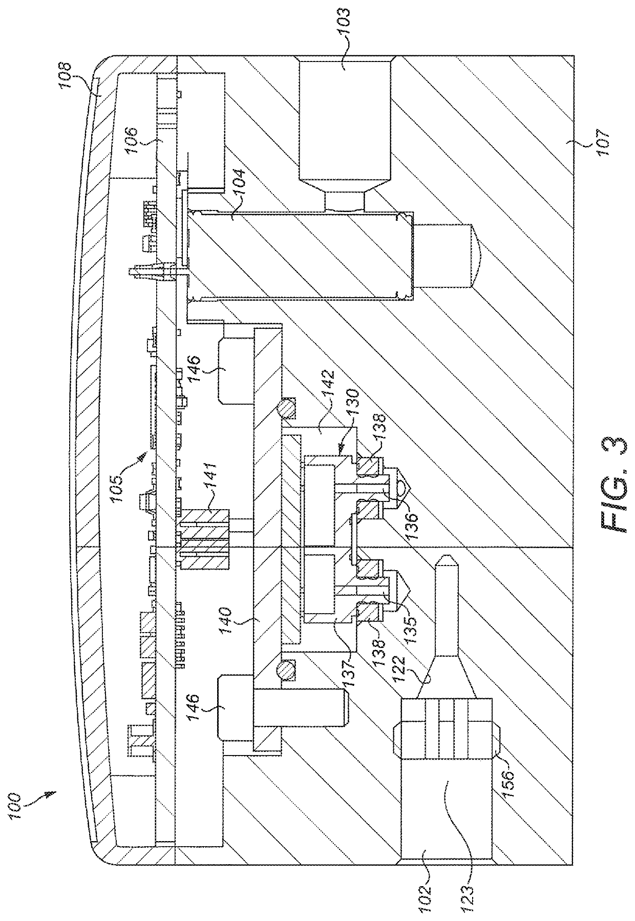
[0056]FIGS. 1 to 6 illustrate a first mass flow controller 100 including a fluid sensing apparatus 120 according to the invention. The mass flow controller 100 includes a housing 101 having a fluid inlet 102 and a fluid outlet 103. The housing 101 contains a fluid control valve 104, for example a proportional valve, and control electronics 105 mounted on a main PCB 106. In this example, the housing 101 comprises a solid body 107 and a lid 108 which is removably fixed to the solid body 107 by screws 109. The fluid control valve 104 is situated along a fluid flow path extending between the fluid inlet 102 and the fluid outlet 103 and is configured to adjust the flow rate through the mass flow controller 100, based on a control signal from the control electronics 105, in order to achieve or maintain a desired flow rate. The fluid inlet 102 and the fluid outlet 103 may be threaded, as shown in FIG. 1, to allow for easy coupling to threaded connectors. Alternatively, the fluid inlet and ...

second embodiment

[0071]Further, in the mass flow controller 200 of the second embodiment, the third location 243 from which the pressure compensation conduit 244 extends is upstream of both of the first and second locations 231, 233, rather than downstream.


PUM


Abstract

There is provided a fluid sensing apparatus comprising a fluid flow channel, at least one fluid conduit in fluid communication with the fluid flow channel, and a fluid sensor having a casing and at least one sensor port in fluid communication with the at least one fluid conduit and providing access into the casing. The fluid sensing apparatus also includes a pressure compensation chamber in which the casing of the fluid sensor is enclosed. The apparatus further includes at least one pressure compensation conduit in fluid communication with the pressure compensation chamber and with the fluid flow channel. Also provided is a mass flow controller including such a fluid sensing apparatus.

Description

FIELD OF THE INVENTION[0001]The present invention relates to a fluid sensing apparatus and in particular to a fluid sensing apparatus for use with a fluid control valve, such as in a mass flow controller or in a mass flow meter.BACKGROUND TO THE INVENTION[0002]Fluid control valves are used in a wide variety of applications to control the flow of a fluid. The fluid being controlled may comprise a gas, a liquid, or a combination thereof. In some situations, the fluid may also include suspended particulates. While fluid control valves vary widely in the specific configuration used to open and close a fluid communication path through the valve, one specific type of valve actuation is performed using a solenoid. In solenoid-actuated valves, an electric current passes through an electromagnetic coil, with the coil typically formed around a magnetic core. The coil generally comprises a wire that is wrapped around a bobbin numerous times resulting in a plurality of so-called turns. The ener...

Claims


Application Information

Patent Timeline
IPC IPC(8): G05D7/06G01F1/88
CPCG05D7/0635G01F1/88G01F15/02G01F15/04G01F15/14G01F15/005G05D7/0623G01F1/50G01F5/005G01F1/6845G01F15/028
Inventor AZZONI, DAVIDEDIAZ, MANUELBLAMPEY, TEDDY
Owner FAS MEDIC SA
Why Eureka
Try Eureka