Auxiliary mechanism of fire hose
An auxiliary mechanism and fire hose technology, which is applied in fire rescue and other directions, can solve the problems such as the hose interface is easy to fall off and pull, and it is difficult to achieve the effect of avoiding direct contact and reducing friction
- Summary
- Abstract
- Description
- Claims
- Application Information
AI Technical Summary
Problems solved by technology
Method used
Image
Examples
Embodiment 1
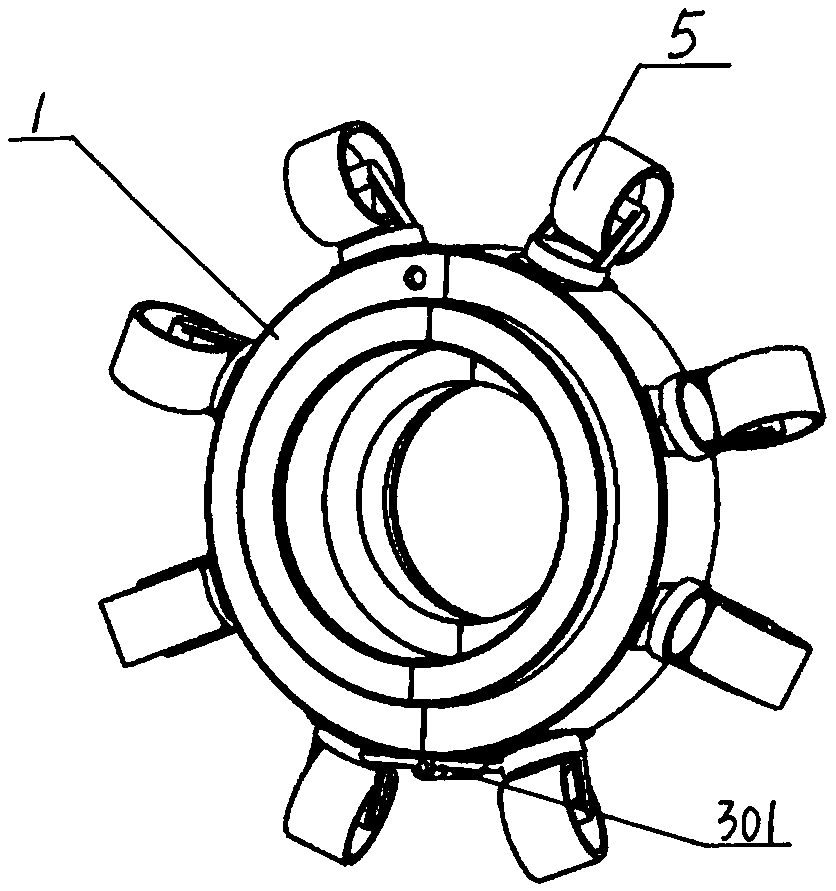
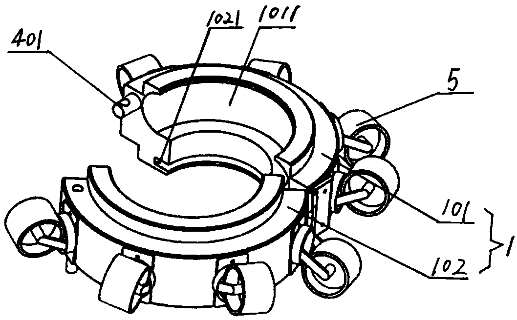
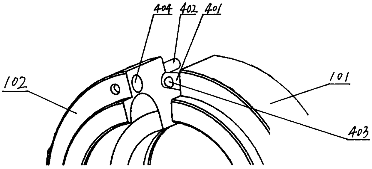
[0027] Present embodiment 1 proposes a kind of fire hose auxiliary mechanism, such as figure 1 , figure 2 as well as image 3 As shown, it includes a body 1, which is an annular body formed by butting two identical semi-annular first hoops 101 and second hoops 102. The inner radial surface of the body has two parallel annular grooves, wherein One annular groove is a female groove 1011 for matching the female end of the hose interface, and the other annular groove is a male groove 1021 for matching the male end of the hose interface. One of the first ferrule and the second ferrule One set of opposite connecting ends are joined by hinges 301, the other set of opposite connecting ends are joined by a locking device, the locking device includes a locking bar 401 and a spring latch 402, and the connecting end of the first hoop is set toward the second The cylindrical locking bar of the hoop, the locking bar is provided with a pin hole 403 perpendicular to its axis, the connectin...
Embodiment 2
[0029] This embodiment 2 proposes a fire hose auxiliary mechanism. This embodiment 2 is basically the same as the above-mentioned embodiment 1, the difference lies in the guiding device on the body, such as Figure 4 As shown, a plurality of evenly distributed one-way wheels 6 are arranged on the radially outer surface of the body 2, the wheel frame of each one-way wheel is connected with the body, and the axis of each one-way wheel is perpendicular to the axis of the body.
Embodiment 3
[0031] This embodiment 3 proposes a fire hose auxiliary mechanism, this embodiment 3 is basically the same as the above embodiment 1, the difference lies in the guiding device on the body, such as Figure 5 As shown, a number of evenly distributed universal balls 7 are arranged on the outer radial surface of the body 3, and the support plates of each universal ball are connected to the body.
PUM
 Abstract
Description
Claims
Application Information
 - R&D
- Intellectual Property
- Life Sciences
- Materials
- Tech Scout
- Unparalleled Data Quality
- Higher Quality Content
- 60% Fewer Hallucinations
Browse by: Latest US Patents, China's latest patents, Technical Efficacy Thesaurus, Application Domain, Technology Topic, Popular Technical Reports.
© 2025 PatSnap. All rights reserved.Legal|Privacy policy|Modern Slavery Act Transparency Statement|Sitemap|About US| Contact US: help@patsnap.com


