An automatic centering cutting mechanism for wire threading trough plate

A technology of threading trough plate and cutting mechanism, which is applied in the direction of feeding device, manufacturing tool, positioning device, etc., can solve the problems of oblique cutting, inaccurate positioning, and affecting cutting effect, etc., and achieves a simple structure and adjustable cutting length Effect

Active Publication Date: 2019-11-19
扬州高新电缆材料有限公司
View PDF6 Cites 0 Cited by
  • Summary
  • Abstract
  • Description
  • Claims
  • Application Information

AI Technical Summary

Problems solved by technology

[0002] The threading trough is an existing trough body for various fixed wires, which has a plurality of positioning jacks. The existing manufacturing method is to punch the middle part of the threading trough plate, then cut it off, and then cut off the middle part of the threading trough plate. The two sides are bent vertically upwards, and the existing cutting process is carried out by manually lifting the threading channel plate, which not only increases the labor intensity of the workers, but also manually lifts and feeds the material, and its positioning is not accurate enough, which is prone to skewing. Problems such as cutting off will affect the cutting effect

Method used


Image

  • An automatic centering cutting mechanism for wire threading trough plate
  • An automatic centering cutting mechanism for wire threading trough plate

Examples


Embodiment Construction

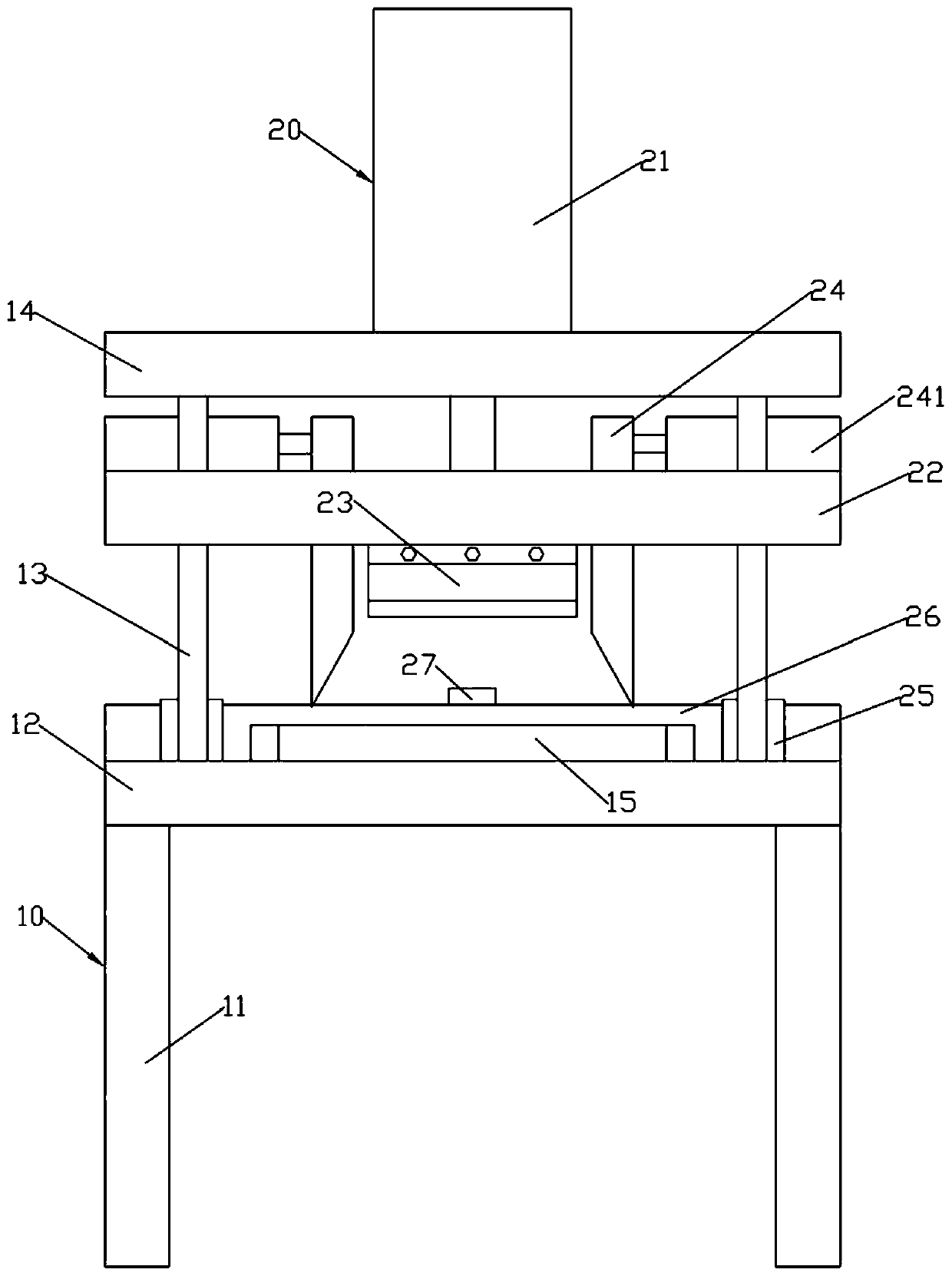
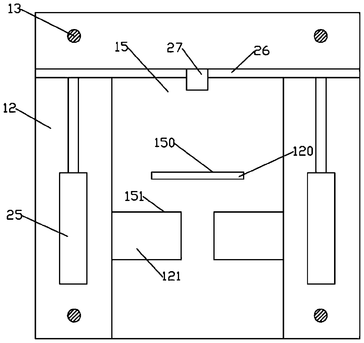
[0014] Such as figure 1 , figure 2 Shown, a kind of automatic centering cutting mechanism for electric wire threading trough comprises frame 10 and cutting device 20; Frame 10 comprises lower support plate 12 and upper support plate 14; Above; the lower end surface of the lower support plate 12 is provided with a number of evenly distributed support feet 11; the upper support plate 14 and the lower support plate 12 are connected into one body by a number of evenly distributed connecting rods 13; the center of the lower support plate 12 is formed with The blanking hole 120 set through the top and bottom;

[0015] Such as figure 1 , figure 2 As shown, the center of the upper end surface of the lower support plate 12 is provided with a cutting support plate 15; the cutting device 20 includes a lifting support plate 22; A cutter 23 is detachably installed in the center of the lower end surface; a pair of centered drive blocks 24 are arranged on the lifting support plate 22 t...


PUM


Abstract

The invention discloses an automatic centered cutting mechanism for electric wire penetrating groove plates. The mechanism comprises a frame and a cutting device; a cutting support plate is arranged in the center of the upper end surface of a lower support plate; a lifting support plate is arranged between the lower support plate and an upper support plate in a lifting mode; a cutter is detachablymounted in the center of the lower end surface of the lifting support plate; a pair of centered driving blocks is arranged on the lifting support plate in a left-right moving mode; the lower edge lines of the approaching end surfaces of the pair of centered driving blocks are formed as chamfering angles; a pair of upper centered avoiding grooves for enabling the centered driving blocks to insertin is formed in the front part of the cutting support plate; the lower support plate is provided with lower centered avoiding grooves, same with the upper centered avoiding grooves, right under the upper centered avoiding grooves; length adjusting blocks are arranged at the back part of the upper end surface of the lower support plate in a front-back sliding mode; and upper stop plates are moldedat the middle parts of the upper end surfaces of the length adjusting blocks. The mechanism is simple in structure and adjustable in cutting length of the electric wire penetrating groove plates, andcan automatically center the electric wire penetrating groove plates.

Description

technical field [0001] The invention relates to the technical field of electronic parts and equipment processing, in particular to an automatically centered cutting mechanism for wire threading trough plates. Background technique [0002] The threading trough is an existing trough body for various fixed wires, on which there are multiple positioning jacks. The existing manufacturing method is to punch the middle part of the threading trough plate, then cut it off, and then cut off the middle part of the threading trough plate. The two sides are bent vertically upwards, and the existing cutting process is carried out by manually lifting the threading channel plate, which not only increases the labor intensity of the workers, but also manually lifts and feeds the material, and its positioning is not accurate enough, which is prone to skewing. Problems such as cutting off will affect the cutting effect. Contents of the invention [0003] The object of the present invention i...

Claims


Application Information

Patent Timeline
Patent Type & Authority Patents(China)
IPC IPC(8): B21D28/02B21D43/00
CPCB21D28/02B21D43/003
Inventor 徐亚维
Owner 扬州高新电缆材料有限公司
Why Eureka
Try Eureka