A steel bar cutting device

A technology for cutting equipment and steel bars, which is applied in the field of steel bar cutting equipment, and can solve the problems of human operator's physical danger and low degree of automation.

Active Publication Date: 2020-09-18
王学凤
View PDF7 Cites 0 Cited by
  • Summary
  • Abstract
  • Description
  • Claims
  • Application Information

AI Technical Summary

Problems solved by technology

[0002] During the construction of bridges, it is often encountered that the program of cutting steel bars in batches has a low degree of automation, and too many manual operations will cause danger to the human body. This invention solves the above problems

Method used


Image

  • A steel bar cutting device
  • A steel bar cutting device
  • A steel bar cutting device

Examples


specific Embodiment approach 1

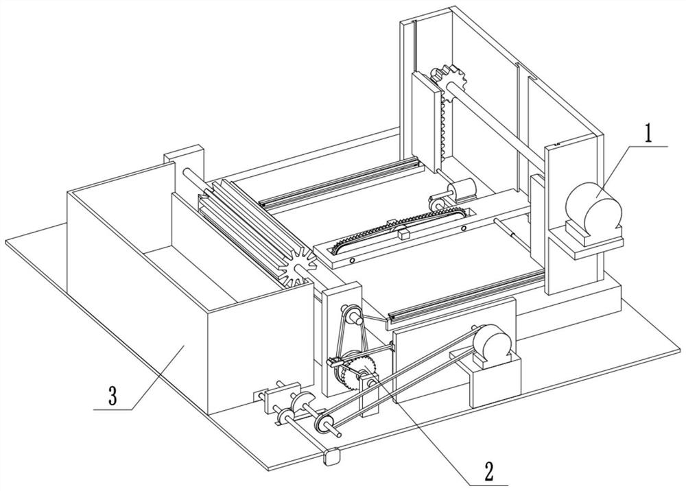
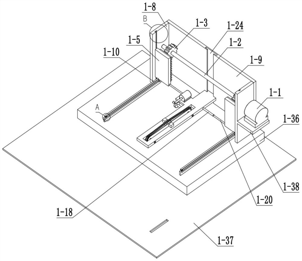
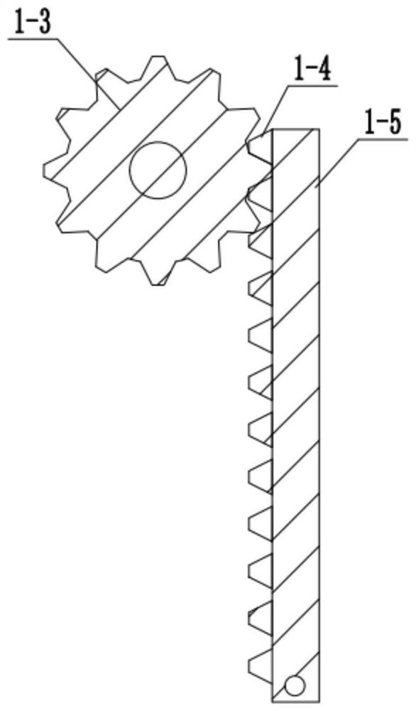
[0033] Combine below Figure 1-19 Describe this embodiment, a steel bar cutting equipment, including a cutting assembly 1, a feeding assembly 2 and a material box assembly 3, characterized in that: the cutting assembly 1 includes a servo motor 1-1, a lifting shaft 1 -2, lifting gear 1-3, lifting rack 1-4, lifting plate 1-5, lifting plate slide rail 1-6, lifting plate chute 1-7, side plate I1-8, side plate II1-9, Lifting rod 1-10, spherical chute 1-11, ball head 1-12, ball head column 1-13, ball head column lug 1-14, turret 1-15, fixed block 1-16, fixed frame 1 -17, threaded sliding cylinder 1-18, T-shaped hole 1-19, support shaft 1-20, cutting frame chute Ⅰ1-21, cutting frame slide rail 1-22, cutting frame 1-23, cutting Frame chute Ⅱ1-24, motor Ⅰ1-25, worm 1-26, worm gear 1-27, worm shaft 1-28, sprocket Ⅰ1-29, chain Ⅰ1-30, tensioning sprocket 1-31, tensioning chain Wheel shaft 1-32, sprocket II 1-33, sprocket II shaft 1-34, cutting knife 1-35, cutting bottom plate 1-36, bott...

specific Embodiment approach 2

[0037] Combine below Figure 1-19 This embodiment will be described. This embodiment will further explain Embodiment 1. The material box assembly 3 includes a sprocket V3-1, a chain III3-2, a sprocket VI3-3, a sprocket VI shaft 3-4, a half Gear 3-5, gear 3-6, material box lifting shaft 3-7, lifting shaft bracket 3-8, handle 3-9, lifting slider Ⅰ 3-10, lifting slider Ⅱ 3-11, carriage 3-12 , Lug Ⅰ3-13, lifting rod Ⅰ3-14, supporting lug Ⅱ3-15, lifting rod Ⅱ3-16, supporting lug Ⅲ3-17, material box lifting plate 3-18 and material box 3-19, sprocket Ⅴ3-1 It is connected with motor Ⅱ shaft 2-2, sprocket Ⅴ3-1, chain Ⅲ3-2, sprocket Ⅵ3-3 sprocket chain, sprocket Ⅴ3-1 and sprocket Ⅵ3-3 transmission ratio is 1:1, chain The wheel Ⅵ 3-3 is connected with the sprocket Ⅵ shaft 3-4, the sprocket Ⅵ shaft 3-4 is connected with the half gear 3-5, the toothed part of the half gear 3-5 is meshed with the gear 3-6, and the gear 3- 6 is connected with the lifting shaft 3-7 of the material box, the ...


PUM


Abstract

The invention relates to the field of bridges, in particular to steel bar cutting equipment. The steel bar cutting equipment comprises a cutting combined body, a feeding combined body and a material box combined body. By means of the steel bar cutting equipment, the problems frequently encountered when a bridge is built that the automation degree of programs for cutting steel bars in batches is low, and danger is generated to human bodies by too much manual operation are solved. To-be-cut steel bars are put into a material box, a threaded sliding barrel is adjusted, a cutter blade slides in the axial direction of a supporting shaft, and the cutting length of the steel bars can be adjusted. The cutter blade moves reciprocatingly up and down so that the steel bars are cut. When the cutting blade moves upwards, a rotary frame is opened, a feeding rotary barrel rotates and the steel bars in the material box are taken out and fall into the space between the rotary frame and a fixing frame through a slant plate, and a lifting plate of the material box does not move. When the cutting blade moves downwards, the rotary frame is closed, the feeding rotary barrel stops rotating, the steel bars are stacked flush and clamped by the rotary frame and the fixing frame and are convenient for the cutting blade to cut, the lifting plate of the material box rises, and uncut steel bars in the material box are lifted and wait to be taken out by rotation of the feeding rotary barrel.

Description

technical field [0001] The invention relates to the field of bridges, in particular to a steel bar cutting device. Background technique [0002] During the construction of bridges, problems such as the low degree of automation of batch cutting of steel bars and the dangers to human health due to excessive manpower operations are often encountered. The present invention solves the above problems. Contents of the invention [0003] The purpose of the present invention is achieved through the following technical solutions: [0004] A steel bar cutting equipment, including a cutting assembly, a feeding assembly and a material box assembly, the cutting assembly includes a servo motor, a lifting shaft, a lifting gear, a lifting rack, a lifting plate, a lifting plate slide rail, a lifting plate Plate chute, side plate Ⅰ, side plate Ⅱ, lifting rod, spherical chute, ball head, ball head post, ball head post lug, turret, fixed block, fixed frame, threaded slide, T-shaped hole, supp...

Claims


Application Information

Patent Timeline
Patent Type & Authority Patents(China)
IPC IPC(8): B21F11/00B21F23/00
CPCB21F11/00B21F23/00
Inventor 罗宇仙王学凤
Owner 王学凤
Why Eureka
Try Eureka