An automatic production device for cutting rod-shaped building materials

A technology for production equipment and building materials, applied in the direction of shearing equipment, metal processing equipment, manufacturing tools, etc., can solve the problems of low work efficiency, inability to adjust the cutting length of materials according to needs, troublesome operation, etc.

Active Publication Date: 2021-10-08
烟台东方轴承有限责任公司
View PDF0 Cites 0 Cited by
  • Summary
  • Abstract
  • Description
  • Claims
  • Application Information

AI Technical Summary

Problems solved by technology

[0004] The purpose of the present invention is to solve the problems of the present invention, which effectively solves the problems of the existing design operation troubles, low work efficiency and the inability to adjust the cutting length of the material according to the needs, and proposes an automatic production device for cutting rod-shaped building materials. The device is easy to operate , the structure is reasonable, it can realize the automatic truncation of rod-shaped building materials and can adjust the length of each section of building materials according to the needs

Method used


Image

  • An automatic production device for cutting rod-shaped building materials
  • An automatic production device for cutting rod-shaped building materials
  • An automatic production device for cutting rod-shaped building materials

Examples


Embodiment 1

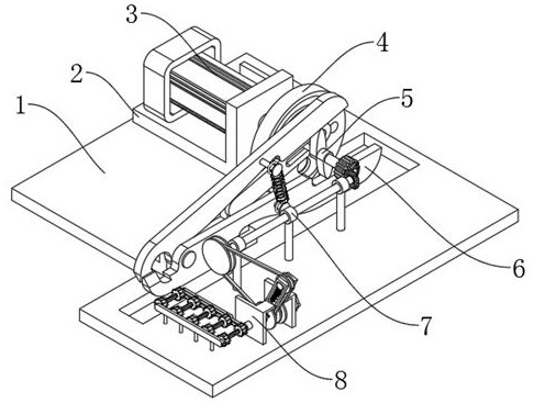
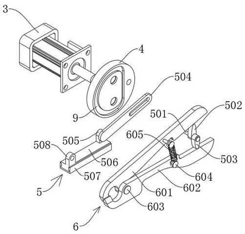
[0029] see Figure 1-4, an automatic production device for cutting rod-shaped building materials, comprising a mounting base 1 and a mounting plate 2, the mounting plate 2 is fixedly connected to the upper surface of the mounting base 1, a servo motor 3 is fixedly connected to the mounting plate 2, and the output of the servo motor 3 A turntable 4 is fixedly connected to the shaft, and the turntable 4 is provided with a motion track groove 9, and the first linkage mechanism 5 is arranged on the motion track groove 9, and the first linkage mechanism 5 matches the motion track groove 9, and the first linkage mechanism 5 A cut-off mechanism 6 is connected, and a movable opening is provided under the cut-off mechanism 6, and the movable opening is opened on the mounting base 1; the second linkage mechanism 7 is also connected to the first linkage mechanism 5, and the second linkage mechanism 7 is connected to the end far away from the servo motor 3. There is a raw material conveyi...

Embodiment 2

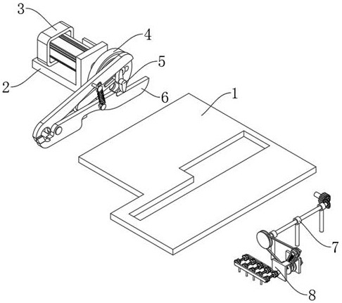
[0035] see Figure 5-7 , based on Embodiment 1, the difference is that;

[0036] The second linkage mechanism 7 includes a second connecting shaft 701 and a first fixed frame 702, the second connecting shaft 701 is fixedly connected with the fifth connecting shaft 603, and the end of the second connecting shaft 701 away from the fifth connecting shaft 603 is fixedly connected with the first A bevel gear 703, the first bevel gear 703 is meshed with the second bevel gear 704, the second bevel gear 704 is fixedly connected to the third connecting shaft 705, the first fixed frame 702 is fixedly connected to the mounting base 1, the third is connected The shaft 705 is rotatably connected to the first fixed frame 702 .

[0037] The raw material conveying device 8 includes a first belt pulley 801 and a fixed vertical plate 802. The first belt pulley 801 is fixedly connected to the end of the third connecting shaft 705 away from the second bevel gear 704, and the fixed vertical plate...

Embodiment 3

[0041] refer to Figure 7 ; Based on Embodiment 1 or 2, the difference is that;

[0042] The raw material conveying device 8 also includes a driving roller 810, a driven roller 812 and a second fixed frame 811. One end of the driving roller 810 is fixedly connected to the end of the fourth connecting shaft 807 away from the threaded sleeve 808, and the other end is rotated with the second fixed frame 811. Connected, the driven rollers 812 are rotatably connected to the second fixed frame 811 , and the driving roller 810 and the driven rollers 812 are also connected around the second linkage belt 813 .

[0043] Since the fourth connecting shaft 807 on which the combination belt pulley 806 is installed is connected with a threaded pipe sleeve 808, the rotating threaded pipe sleeve 808 can adjust the position of the combination belt pulley 806 on the fourth connecting shaft 807, so that the first linkage belt can be adjusted on the fourth connecting shaft 807. The track on the c...


PUM


Abstract

The invention discloses an automatic production device for cutting rod-shaped building materials, which belongs to the technical field of production devices. An automatic production device for cutting rod-shaped building materials, including a mounting base and a mounting plate, the mounting plate is fixedly connected to the upper surface of the mounting base, a servo motor is fixedly connected to the mounting plate, a turntable is fixedly connected to the output shaft of the servo motor, and the turntable There is a movement track groove on the top, and a first linkage mechanism is arranged on the movement track groove. The first linkage mechanism matches the movement track groove. The first linkage mechanism is connected with a cut-off mechanism. On the mounting base; the first linkage mechanism is also connected with a second linkage mechanism, and the end of the second linkage mechanism away from the servo motor is connected with a raw material conveying device, and the raw material conveying device is matched with the cutting mechanism; the present invention effectively solves the problem of existing design operations Trouble, low work efficiency and the problem of not being able to adjust the length of the material cut by itself according to the needs.

Description

technical field [0001] The invention relates to the technical field of production devices, in particular to an automatic production device for cutting rod-shaped building materials. Background technique [0002] With the development of the construction industry, the demand for some rod-shaped building materials such as steel bars and anchors has gradually increased. In the production process of the above-mentioned rod-shaped building materials, it is often necessary to cut off the rod-shaped raw materials for the next step. One-step production and manufacturing work, some small manufacturers complete the cut-off work of raw materials through manual operation, which is time-consuming, labor-intensive, low-efficiency and has certain safety hazards. Therefore, it is necessary to design an automatic production device for cutting rod-shaped building materials. It is very necessary. [0003] At present, the rod-shaped building material cutting devices that already exist on the ma...

Claims


Application Information

Patent Timeline
Patent Type & Authority Patents(China)
IPC IPC(8): B23D17/00B23D17/02
CPCB23D17/00B23D17/02
Inventor 尉莺凡张艳鑫张玲玲张天闯魏明亮
Owner 烟台东方轴承有限责任公司
Why Eureka
Try Eureka