An automatic cutting device for the production of rod-shaped building materials

A technology for cutting devices and building materials, which is applied in the direction of shearing devices, shearing machine accessories, shearing machine equipment, etc., and can solve problems such as troublesome operation, fixed structure, and low work efficiency

Active Publication Date: 2020-06-02
南通市水利勘测设计研究院有限公司
View PDF11 Cites 0 Cited by
  • Summary
  • Abstract
  • Description
  • Claims
  • Application Information

AI Technical Summary

Problems solved by technology

[0004] The purpose of the present invention is to solve the problems of troublesome operation, low work efficiency, fixed structure, easy failure and inconvenient maintenance in the existing design, and propose an automatic cutting device for the production of rod-shaped building materials. The device is simple in operation and reasonable in structure , which is convenient for maintenance and can realize the automatic truncation of rod-shaped building materials

Method used


Image

  • An automatic cutting device for the production of rod-shaped building materials
  • An automatic cutting device for the production of rod-shaped building materials
  • An automatic cutting device for the production of rod-shaped building materials

Examples


Embodiment 1

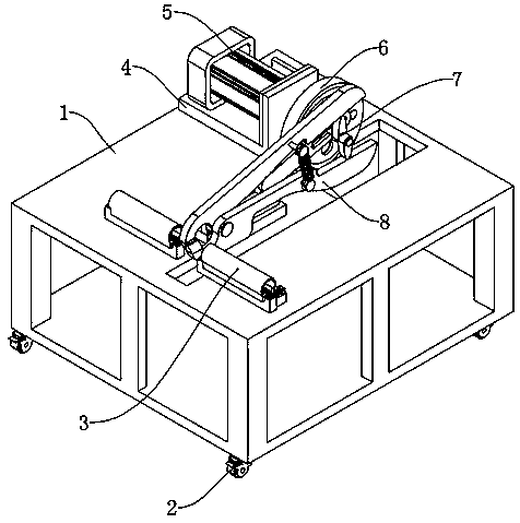
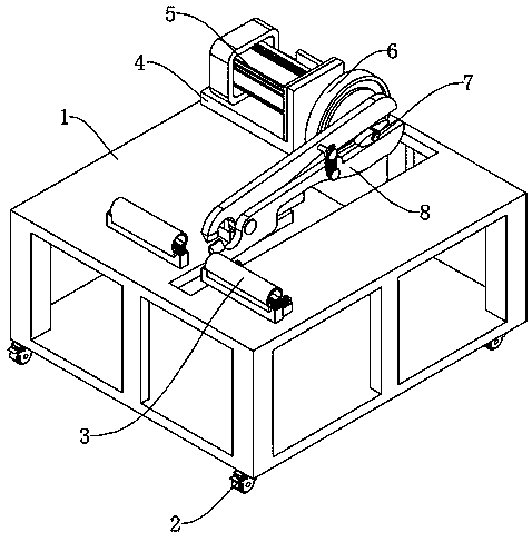
[0028] see Figure 1-4, an automatic cutting device for the production of rod-shaped building materials, including a mounting frame 1 and a roller 2, the roller 2 is fixedly connected to the four corners of the bottom surface of the mounting frame 1, a braking device is also fixedly connected to the roller 2, and the upper surface of the mounting frame 1 is provided with The raw material conveying device 3, the raw material conveying device 3 includes a raw material input end and a raw material output end, there is a gap between the raw material input end and the raw material output end, a movable opening is arranged under the gap, and the movable opening is arranged on the upper surface of the mounting frame 1, The upper surface of the mounting frame 1 is also fixedly connected with a first mounting base 4, the first mounting base 4 is fixedly connected with a servo motor 5, the output shaft of the servo motor 5 is fixedly connected with a turntable 6, and the turntable 6 is p...

Embodiment 2

[0032] see Figure 5 , based on Embodiment 1, the difference is that;

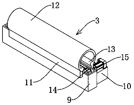
[0033] The second linkage mechanism 14 includes a raw material conveying roller 16, the side wall of the raw material conveying roller 16 is fixedly connected with a linkage gear 17, and the end of the linkage gear 17 away from the raw material conveying roller 16 is fixedly connected with a connecting shaft 18, which is close to the connecting shaft 18 of the drive motor 15 It is fixedly connected with the output shaft of the driving motor 15, and the connecting shaft 18 away from the driving motor 15 is rotationally connected with the inner side wall of the installation groove. The interlocking gear 17 is surrounded by an interlocking belt 19, and the inner wall of the interlocking belt 19 is provided with a gear groove. Groove matches with linkage gear 17.

[0034] The present invention is equipped with a raw material conveying device 3 on the device body. When in use, the manufacturing raw materials o...

Embodiment 3

[0036] refer to Figure 6-7 ; Based on Embodiment 1 or 2, the difference is that;

[0037] Cutting mechanism 8 comprises a first cut-off frame 29 and a second cut-off frame 30, the truncated end of the first cut-off frame 29 and the second cut-off frame 30 is provided with a cut-off edge, the junction of the first cut-off frame 29 and the second cut-off frame 30 A first connection shaft 31 is provided, and the first cut-off frame 29 is rotatably connected with the second cut-off frame 30 by the first connection shaft 31. The first cut-off frame 29 and the second cut-off frame 30 are also fixedly connected with a fixed rod 32, the fixed rod 32 is fixedly connected with spring 33.

[0038] The first linkage mechanism 7 includes a second connecting shaft 21, the second connecting shaft 21 is fixedly connected to the turntable 6, and the end of the second connecting shaft 21 away from the turntable 6 is also fixedly connected with a first arc-shaped adjustment block 22 and a seco...


PUM


Abstract

The invention discloses an automatic cutting-off device for production of rod-shaped building materials, and belongs to the technical field of mechanical production. The automatic cutting-off device for production of the rod-shaped building materials comprises a mounting frame and rollers, the rollers are fixedly connected to the four corners of the bottom surface of the mounting frame, a brake stopping device is further fixedly connected to each roller, a raw material conveying device is arranged on the upper surface of the mounting frame, the raw material conveying device comprises a raw material input end and a raw material output end, a gap is formed between the raw material input end and the raw material output end, a movable opening is formed below the gap, the movable opening is formed in the upper surface of the mounting frame, a first mounting seat is further fixedly connected to the upper surface of the mounting frame, a servo motor is fixedly connected to the first mountingseat, an output shaft of the servo motor is fixedly connected with a rotating disc, and a moving track groove is formed in the rotating disc. According to the automatic cutting-off device for the production of the rod-shaped building materials, the problems that in the case of an existing design, the operation is troublesome, the working efficiency is low, the structure is fixed, faults are proneto be caused, and the maintenance is inconvenient to perform are effectively solved.

Description

technical field [0001] The invention relates to the technical field of mechanical production, in particular to an automatic cutting device for rod-shaped building material production. Background technique [0002] With the development of the construction industry, the demand for some rod-shaped building materials such as steel bars and anchors has gradually increased. In the production process of the above-mentioned rod-shaped building materials, it is often necessary to cut off the rod-shaped raw materials for the next step. One-step production and manufacturing work, some small manufacturers complete the cut-off work of raw materials through manual operation, which is time-consuming, labor-intensive, low-efficiency and has certain safety hazards. Therefore, it is necessary to design an automatic cut-off device for rod-shaped building materials production. It is very necessary. [0003] At present, the rod-shaped building material cutting devices that already exist on the ...

Claims


Application Information

Patent Timeline
Patent Type & Authority Patents(China)
IPC IPC(8): B23D15/02B23D15/12B23D33/02
CPCB23D15/02B23D15/12B23D33/02
Inventor 赵杰高学民
Owner 南通市水利勘测设计研究院有限公司
Why Eureka
Try Eureka