
Flexible duct with shrinkage-proof film

a flexible duct and shrinkage-proof film technology, applied in the field of flexible pipes, can solve the problems of large influence on the sealing sheath

Inactive Publication Date: 2005-01-18
TECH FRANCE SA
View PDF30 Cites 52 Cited by
  • Summary
  • Abstract
  • Description
  • Claims
  • Application Information

AI Technical Summary

Benefits of technology

The objective of the invention is to propose, within the context of a flexible pipe, a carcass-covering system that serves as a heat shield for the extruded plastic sheath so as to prevent the formation of shrinkage cavities, but does not have the drawbacks of the aforementioned solutions and enables it to be put into place simply.
By winding the tapes with a long pitch, the scrapers of the extruder are prevented from lifting these tapes up and the length of tapes needed for covering the entire length of the flexible pipe is thus limited, which avoids having to recharge the taping unit during production.
The constituent material of the tapes may be of the reinforced or unreinforced heat-shrinkable type, which may improve the formation of the indentations.

Problems solved by technology

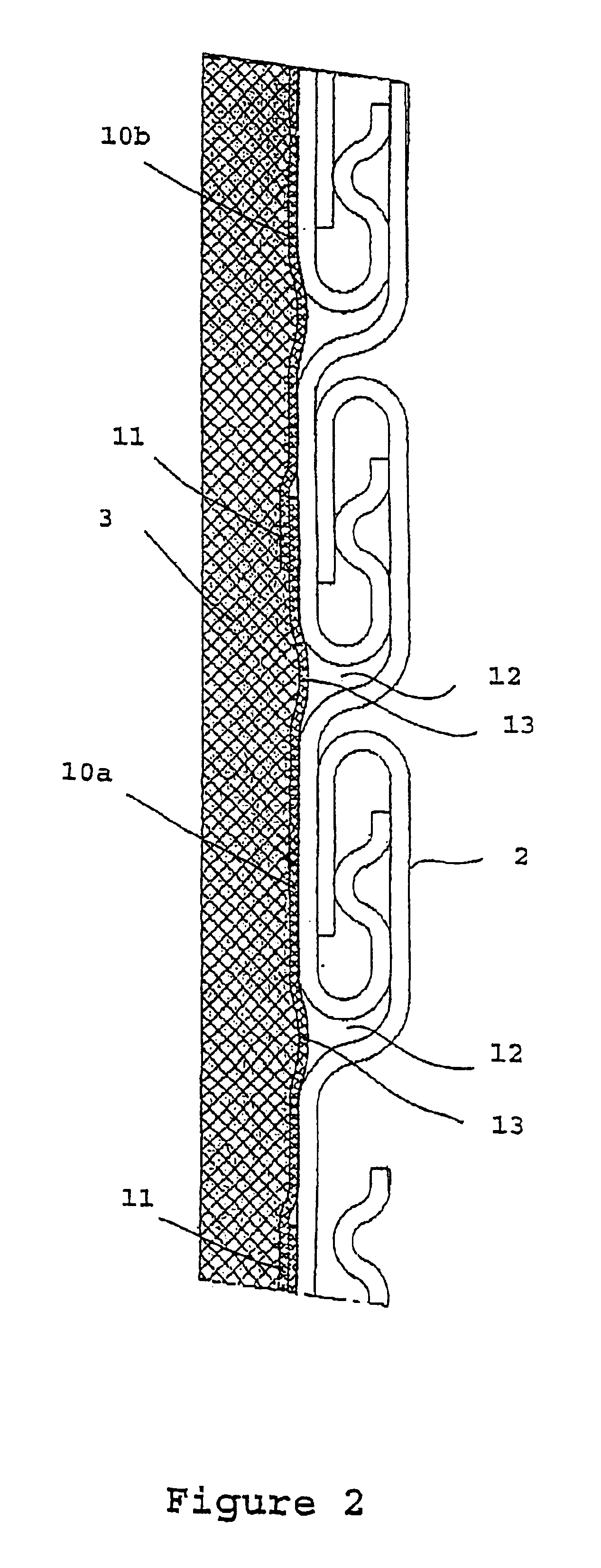
This overlapping of the tapes may create a defect on the internal surface of the extruded sheath, but this possible defect is a long-pitch helical defect, and therefore does not have a great influence on the sealing sheath.

Method used


Image

  • Flexible duct with shrinkage-proof film
  • Flexible duct with shrinkage-proof film
  • Flexible duct with shrinkage-proof film

Examples


Embodiment Construction

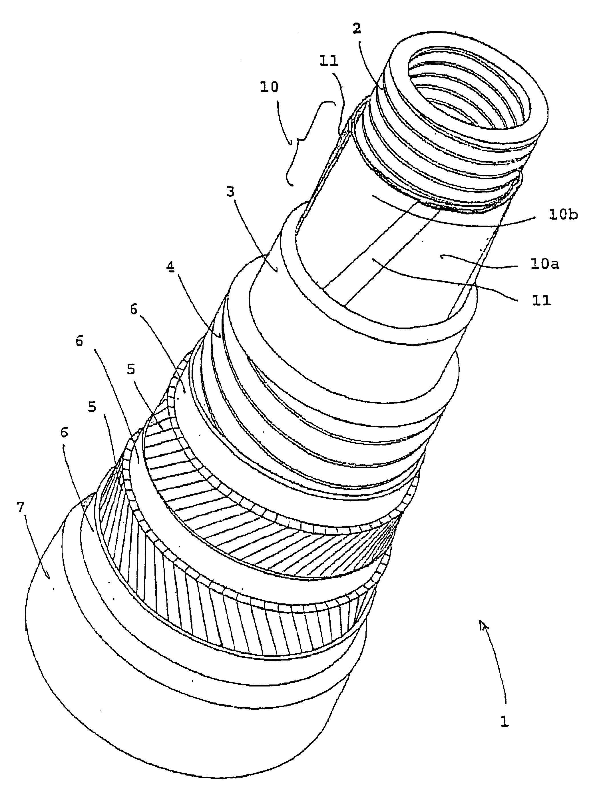
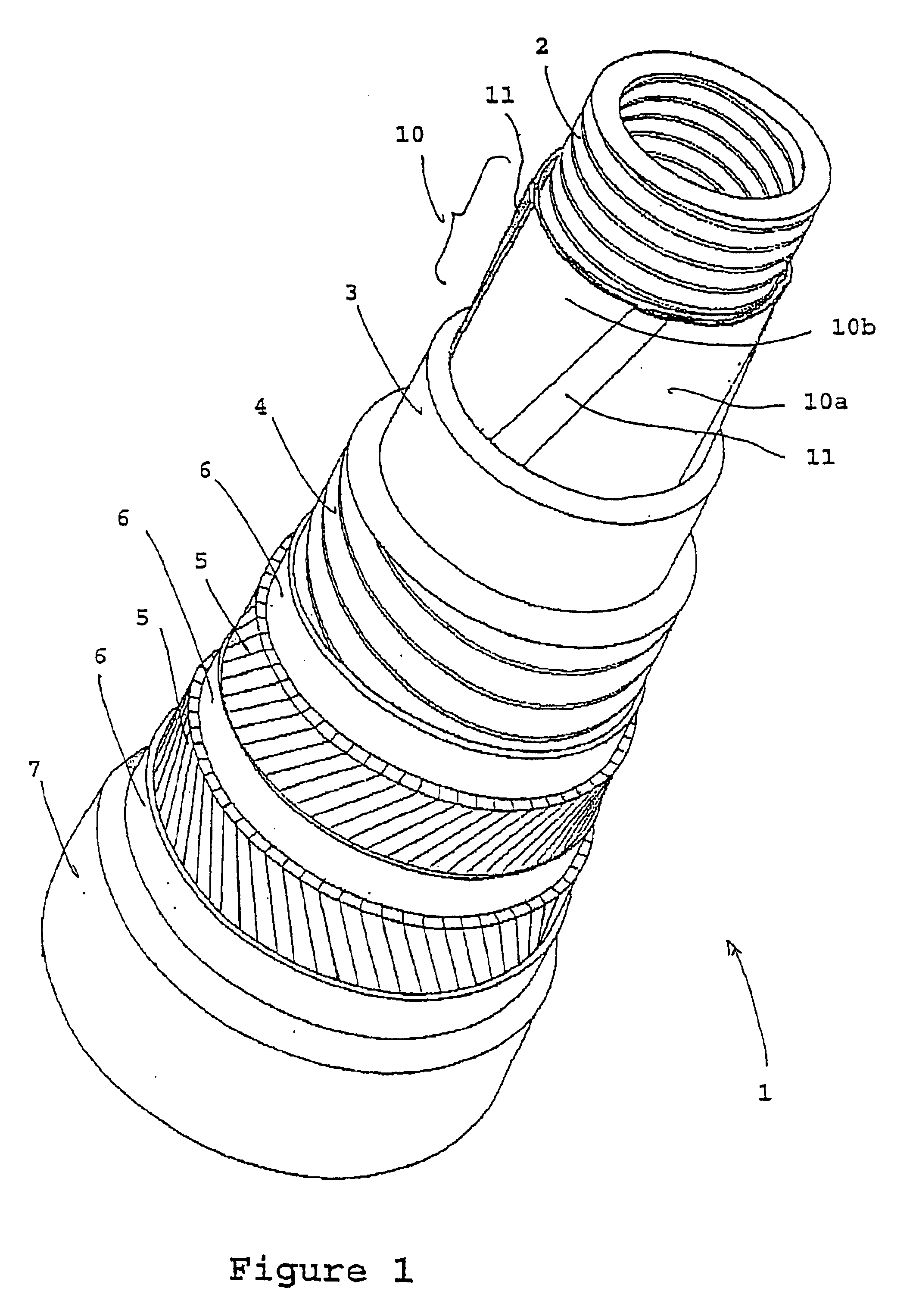
A rough-bore flexible pipe 1 comprises, from the inside outward:a flexible metal tube or carcass 2, formed by a short-pitch helical winding (that is to say one with a winding angle close to 90°) of a metal strip or wire of predetermined cross section;an internal sealing or pressure sheath 3 made of a polymer, placed around the carcass 2;a pressure vault 4 resistant mainly to the pressure developed by the fluid in the sealing sheath and formed by the short-pitch helical winding (that is to say one with a winding angle close to 90°) around the internal sheath of one or more interlocked profiled metal wires (which may or may not be self-interlockable); the profiled wires have a Z-shaped or T-shaped cross section or one derived therefrom (teta or zeta), or a U-shaped or I-shaped cross section;one or more armour plies 5 wound with a long pitch, for example two crossed tensile armour plies whose lay angle, measured along the longitudinal axis of the pipe, is less than 60°;optionally, one ...


PUM


Abstract

The invention concerns a flexible duct (1) comprising from inside outwards a carcass (2) produced by a short-pitched metallic helical winding forming butt gaps (12), an overlapping layer (10) acting as a heat shield consisting of helically wound plastic strips (10a, 10b), a sealed inner pressure sheath (3), extruded in plastic on said overlapping layer (10), at least an armouring web (5) and at least an outer sealing sheath (7). The invention is characterised in that the overlapping strips (10a, 10b) are wound at a winding angle less than 35°.

Description

BACKGROUND OF THE INVENTIONThe present invention relates to a flexible pipe that can be used for transporting fluids, such as hydrocarbons for example.Several types of flexible pipe are used. Some flexible pipes comprise, from the inside outward, an internal sealing sheath made of a plastic, an elastomer or another relatively flexible suitable material; an unsealed flexible metal tube that has to withstand the forces developed by the pressure of the fluid flowing in the pipe; one or more armor plies and at least one external sealing sheath made of a polymeric material. This type of flexible pipe is often called a smooth-bore pipe by experts in the field.Other flexible pipes, called rough-bore pipes, comprise, from the inside outward, an unsealed flexible metal tube, called a carcass, formed by a profile wound in turns and mutually interlocked, such as, for example, an interlocked strip or an interlocked shaped wire such as a T-shaped, U-shaped, S-shaped or zeta-shaped wire; an inter...

Claims


Application Information

Patent Timeline
Patent Type & Authority Patents(United States)
IPC IPC(8): F16L11/08
CPCF16L11/16F16L11/083
Inventor ESPINASSE, PHILIPPE FRAN.CEDILLA.OIS
Owner TECH FRANCE SA
Learn More