A new type of continuous pressing cutting machine

A cutting machine and cutting mechanism technology, applied in the direction of forming tools, shearing devices, manufacturing tools, etc., can solve the problems of increasing equipment manufacturing costs, reducing processing accuracy and production efficiency, and inability to complete, so as to achieve high processing accuracy and improve The effect of improving processing efficiency and production efficiency

Active Publication Date: 2019-10-22
ANHUI KINGPOWER EQUIP & MOLD MFR
View PDF6 Cites 0 Cited by
  • Summary
  • Abstract
  • Description
  • Claims
  • Application Information

AI Technical Summary

Problems solved by technology

Most of the existing profiling and cutting machines are manually transported to the profiling mold, and then cut at a specific length with a cutter. In addition to profiling of a specific shape and cutting of a specific length, other functions cannot be completed
When it is necessary to laminate, press and punch holes at the beginning of the cut workpiece to facilitate installation and assembly, or to adjust the cutting length of the plate according to different specifications of the product, it is also necessary to redevelop the matching cutting machine according to the cutting length, and add a punching device at the same time. Increased human cost of equipment manufacturing, reduced processing accuracy and production efficiency

Method used


Image

  • A new type of continuous pressing cutting machine
  • A new type of continuous pressing cutting machine
  • A new type of continuous pressing cutting machine

Examples


Embodiment Construction

[0025] The technical solutions in the embodiments of the present invention will be clearly and completely described below in conjunction with the embodiments of the present invention. Apparently, the described embodiments are only some of the embodiments of the present invention, not all of them. Based on the embodiments of the present invention, all other embodiments obtained by persons of ordinary skill in the art without creative efforts fall within the protection scope of the present invention.

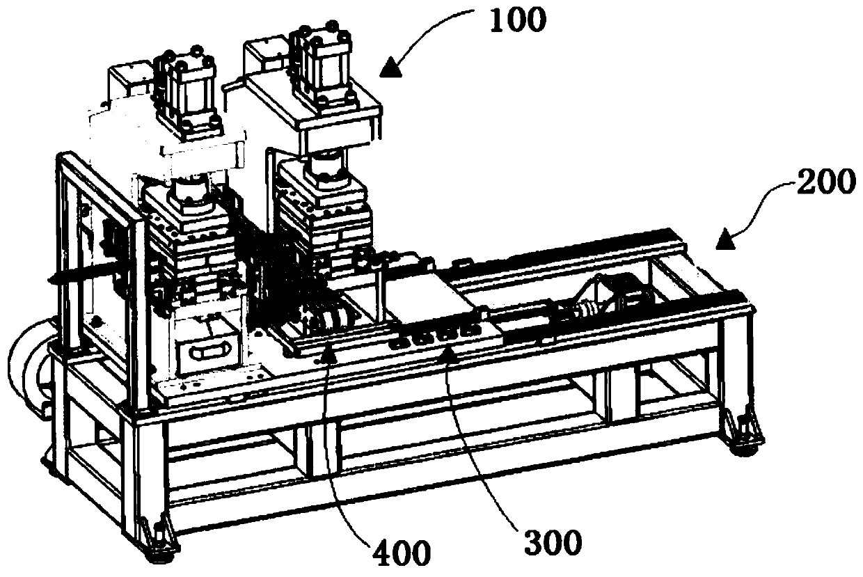
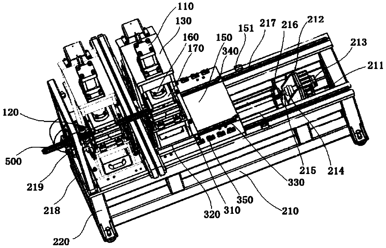
[0026] see figure 1 As shown, this embodiment provides a new type of continuous profile cutting machine, which is used for continuous press forming, cutting, punching, and blanking of sheet metal, including a profile cutting assembly 100, a base assembly 200, and a sliding positioning assembly 300 , The unloading belt assembly 400. Specifically, the profiling cutting assembly 100 is arranged on the top of the base assembly 200. The profiling cutting assembly 100 includes a first ...


PUM


Abstract

The invention discloses a novel continuous profile cutting machine, which comprises a profile cutting assembly, a base assembly, a sliding positioning assembly, and a feeding belt assembly; the profile cutting assembly includes: an upper stamping oil cylinder, a profile cutting punching die, an outer The installation frame, the lower stamping cylinder, and the lower sliding installation plate; the base assembly includes a support base and a support foot, and the servo motor is connected with a ball screw pair through a coupling, and a wire is provided on the side of the ball screw pair near the coupling. The rod bearing seat and the far end of the ball screw pair are connected with the screw nut seat in the middle of the back of the lower sliding mounting plate; the sliding positioning assembly includes a side support plate, a sliding support plate, and a sliding positioning guide rail, and the side support plate is located at the bottom of the lower formwork. The present invention can accurately and continuously carry out the pressing, cutting and punching of the end of the plate with the bending edge, and the cutting distance between the pressing and cutting components can be adjusted, which greatly reduces the cost of the continuous pressing and cutting equipment and improves the production efficiency. efficiency.

Description

technical field [0001] The invention relates to the technical field of profiling processing equipment, in particular to a novel continuous profiling cutting machine. Background technique [0002] In order to process plates with specific shapes and bending shapes to meet the needs of different industries and products, there are various profile cutting machines on the market. Most of the existing profiling and cutting machines are manually transported to the profiling mold, and then cut at a specific length with a cutter. In addition to profiling of a specific shape and cutting of a specific length, other functions cannot be completed. When it is necessary to laminate, press and punch holes at the beginning of the cut workpiece for easy installation and combination, or to adjust the cutting length of the plate according to different specifications of the product, it is also necessary to redevelop the matching cutting machine according to the cutting length, and add a punching ...

Claims


Application Information

Patent Timeline
Patent Type & Authority Patents(China)
IPC IPC(8): B23P23/04B23D31/00B21D35/00B21D37/10
Inventor 陈轩陈安伟
Owner ANHUI KINGPOWER EQUIP & MOLD MFR
Why Eureka
Try Eureka