
Manufacturing method of injection mold and 3D printing injection mold

A production method and injection mold technology, applied in the field of 3D printing, can solve problems such as long printing time, and achieve the effect of reducing raw materials, ensuring heat dissipation performance, and ensuring cooling effect

Pending Publication Date: 2018-12-18
ZHUHAI GREE PRECISION MOLD CO LTD +1
View PDF11 Cites 10 Cited by
  • Summary
  • Abstract
  • Description
  • Claims
  • Application Information

AI Technical Summary

Problems solved by technology

[0004] Therefore, the technical problem to be solved by the present invention is to overcome t

Method used


Image

  • Manufacturing method of injection mold and 3D printing injection mold
  • Manufacturing method of injection mold and 3D printing injection mold
  • Manufacturing method of injection mold and 3D printing injection mold

Examples


Embodiment 1

[0029] The present embodiment provides a kind of manufacturing method of injection mold, described following steps:

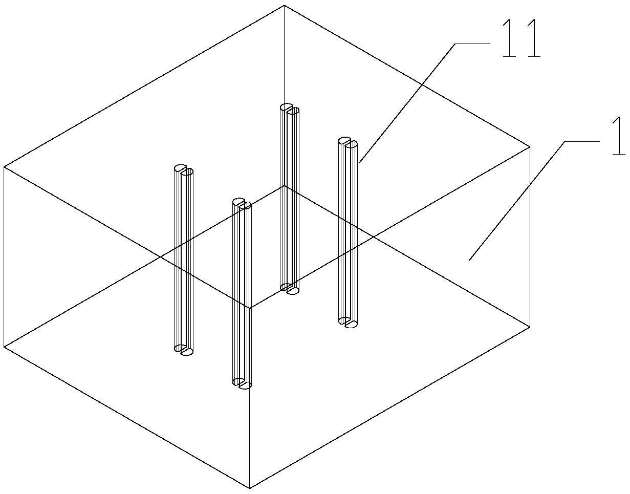
[0030] Select a piece of beryllium copper base, and process a straight waterway inside the beryllium copper part. In this step, if figure 2 As shown in , set four through holes consistent with the distribution of the final beryllium copper part on the beryllium copper base to form a straight waterway. In this step, the straight waterway can be directly processed by CNC technology.

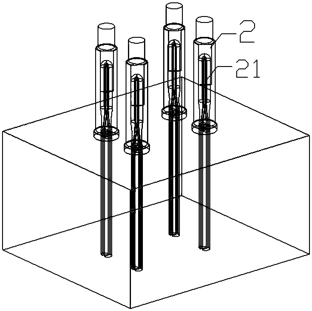
[0031] Immediately afterwards, as image 3 As shown, a steel part is processed by 3D printing technology above the beryllium copper part, and a conformal waterway is arranged inside the steel part, and the conformal waterway is connected with the linear waterway. In this step, the conformal waterway needs to be involved in advance as needed.

[0032] Through the above two steps, the body of the injection mold has been obtained. Since the lower part of the injection mold is still...

Embodiment 2

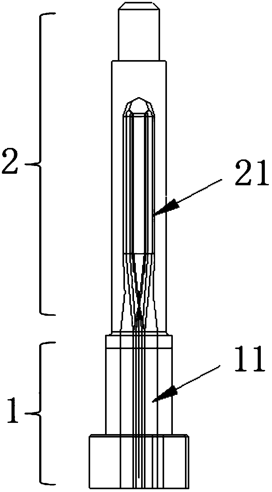
[0037] This embodiment provides a 3D printing injection mold, which is made by the manufacturing method provided in Embodiment 1, such as figure 1 As shown, the entire 3D printing injection mold includes: a beryllium copper part, which is provided with a linear waterway inside; The straight line waterway is connected.

[0038] In this embodiment, the steel part is made of MS1 material, which has high hardness; at the same time, the thermal conductivity of beryllium copper is better. Finally, the entire injection mold combines the high hardness and wear resistance of MS1 material and the fast cooling performance of beryllium copper. , by adopting the 3D graft printing method, the two metals are grafted and printed as a whole, so that the mold parts have the characteristics of high hardness, wear resistance and efficient cooling at the same time.

[0039] In this example, if figure 1 As shown, the shape of the injection mold is a linear tubular structure. However, the injecti...


PUM


Abstract

The invention provides a manufacturing method of an injection mold and a 3D printing injection mold. According to the manufacturing method of the injection mold, straight line water paths are machinedin a beryllium copper portion, and then steel portions are machined on the beryllium copper portion; and the steel portions are internally provided with shape follow-up water paths, and the shape follow-up water paths are connected with the straight line water paths. According to the manufacturing method of the injection mold, the injection mold is divided into two parts, one part is provided with a shape follow-up water path part, and the other part is provided with a straight line water path part. The shape follow-up water path part adopts 3D printing, and the straight line water path partis made of beryllium copper. According to the manufacturing method, only the steel portions need to adopt 3D printing, the method of 3D printing is generally used in comparison with a conventional mold, and the overall time consumption and consumed raw materials are greatly reduced; and meanwhile, the beryllium copper portion is provided with the straight line water paths to communicate with the shape follow-up water paths to ensure the own heat dissipation performance of the mold.

Description

technical field [0001] The invention relates to the technical field of 3D printing, in particular to an injection mold for grafting dissimilar metals and a method for making the injection mold. Background technique [0002] 3D printing is a technology that uses bondable materials such as powdered metal or plastic to construct objects by layer-by-layer printing. [0003] In the existing technology, the overall MS1 metal printing method is often used to make injection molds. The entire injection mold is printed by 3D printing equipment as a whole. The 3D printing itself can print between 45-75g per hour. If you print a whole For injection molds, the printing time consumed is longer. Contents of the invention [0004] Therefore, the technical problem to be solved by the present invention is to overcome the defect in the prior art that the printing time of the injection mold made by 3D printing is relatively long. [0005] For this reason, the present invention provides a ki...

Claims


Application Information

Patent Timeline
IPC IPC(8): B29C33/38B29C45/73B33Y80/00
CPCB29C33/3842B29C45/7312B33Y80/00
Inventor 黄如周刘路黄国军黄泽坚
Owner ZHUHAI GREE PRECISION MOLD CO LTD
Learn More