Keel separation wall and mounting method thereof

A keel and ground keel technology, applied in the direction of walls, building components, buildings, etc., can solve the problems of slow fixing speed and narrow space, and achieve the effect of fast and convenient fixing.

Inactive Publication Date: 2018-12-18
中建津泓(天津)建筑装配科技集团有限公司
View PDF5 Cites 1 Cited by
  • Summary
  • Abstract
  • Description
  • Claims
  • Application Information

AI Technical Summary

Problems solved by technology

[0005] The disadvantage of the connection structure at the male corners above is that the shapes of the first vertical keel 81 and the second vertical keel 91 are generally grooved, and the groove bottom of the first vertical keel 81 is generally the same as that of the second vertical keel 91. The side wall of the groove is fixed. When screw connection or riveting is used, it needs to be operated from the notch of the first vertical keel 81. The space is small and the fixing speed is slow.

Method used


Image

  • Keel separation wall and mounting method thereof
  • Keel separation wall and mounting method thereof
  • Keel separation wall and mounting method thereof

Examples


Embodiment 1

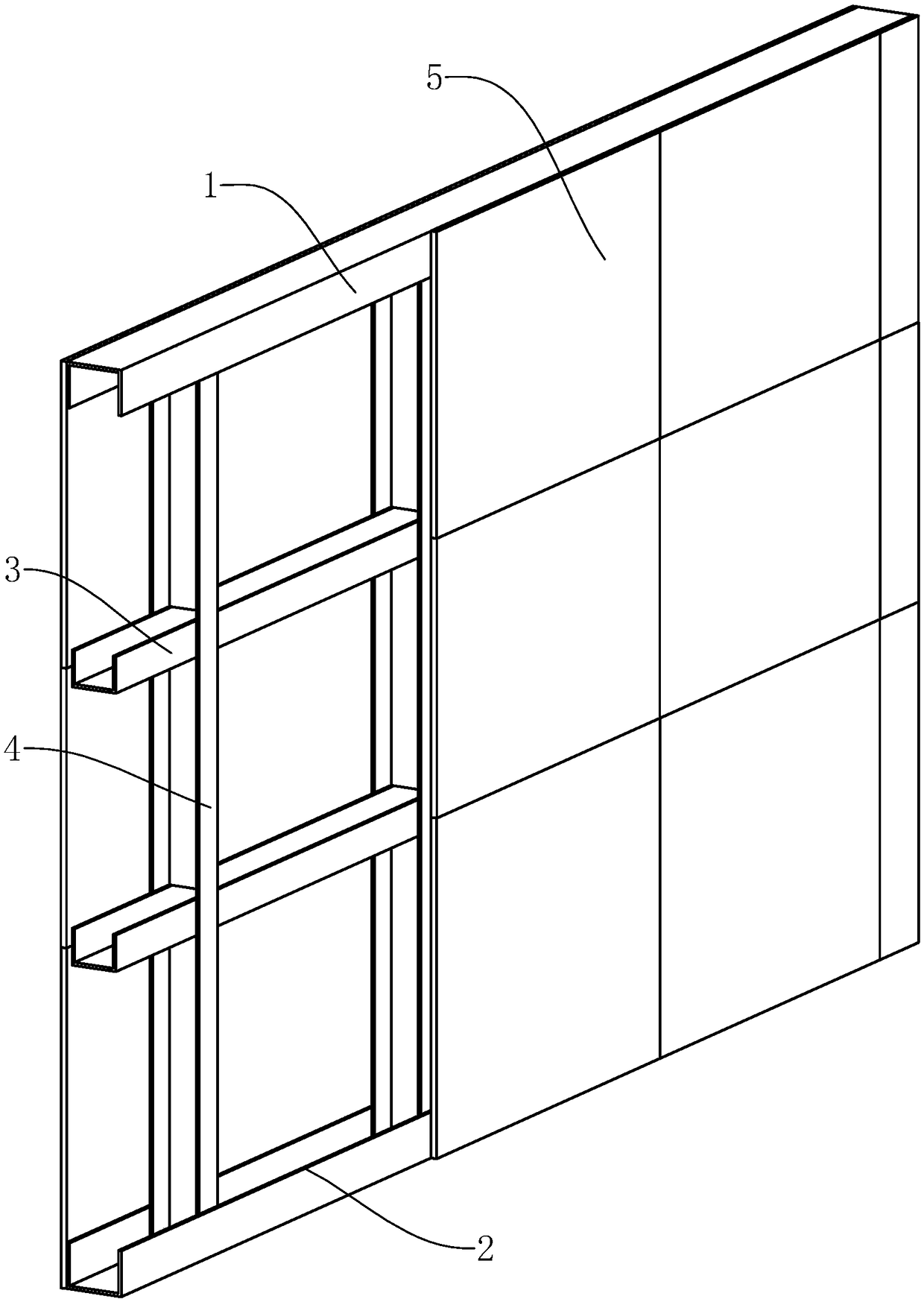
[0034] Such as figure 1 As shown, a keel partition wall includes multiple partition walls. The partition wall includes a top keel, a ground keel 2, a horizontal brace keel 3, a vertical keel 4 and a decorative panel 5. The top keel 1 and the ground keel 2 and the cross-bracing keel 3 are arranged horizontally and in parallel in the same partition wall, the vertical keel 4 is arranged vertically and fixedly connected with the top joist 1, the ground joist 2 and the cross-bracing joist 3 respectively, and the decorative panels are pasted Merged and fixed on both sides of the keel formed by the top keel 1, the ground keel 2 and the cross brace keel 3.

[0035] In the process of setting the keel of the partition wall, firstly, according to the designed wall position, the wall position line is released on the ground, and the line is led to the ceiling and side walls; The keel 2 is generally fixed to the ceiling and the ground respectively by nailing the top keel 1 and the ground k...

Embodiment 2

[0050] A method for installing a keel partition wall, comprising the following steps:

[0051] S1. Wall position setting: according to the wall position determined by the design, lay out the wall position line on the ground, and lead the line to the ceiling and side walls, so that the top keel 1, ground keel 2 and edge keel 2 can be easily positioned through the wall position line. The vertical keel 4 at the free end of the wall avoids misalignment when the keel of the partition wall is installed.

[0052] S2. Install the keel: install the top keel 1 and the ground keel 2 according to the position of the wall line, insert the vertical keel 4 between the top keel 1 and the ground keel 2, and connect the vertical keel 4 and the top keel 1 and along the keel 2 are fixed, horizontally fix the horizontal support keel 3 on the vertical keel 4, the specific steps are as follows:

[0053]S21. Check the smoothness of the ceiling, ground and wall that fit the roof joist 1, the ground j...


PUM


Abstract

The invention relates to a keel separation wall, and particularly to a keel separation wall and a mounting method thereof. The keel separation wall comprises a plurality of separation walls. An external corner part is formed between two adjacent separation walls which are vertical with each other. The connecting structure of the external corner part comprises a transverse separation wall and a longitudinal separation wall. The transverse separation wall comprises a first vertical keel, a first inner panel and a first external panel at the external corner part. The longitudinal separation wallcomprises a second vertical keel, a second inner panel and a second external panel at the external corner part. The trough bottom of the first vertical keel, the second inner panel, and one side, which is next to the second inner panel, of the second vertical keel are respectively provided with an insertion hole. The first vertical keel, the second inner panel and the second vertical keel are fixed through a fixing member. The fixing member comprises a force applying part, an insertion rod and a fixing part. The force applying cannot pass through the insertion hole. The fixing part can pass through the insertion hole, and furthermore the highest length of the fixing part is larger than the highest width of the insertion hole. According to the keel separation wall, the longitudinal separation wall and the transverse separation wall at the external corner part are fixed by means of the fixing member, thereby realizing an effect of quickly and conveniently fixing the external corner part.

Description

technical field [0001] The invention relates to a keel partition wall, in particular to a keel partition wall and an installation method. Background technique [0002] The keel partition wall is a new type of building partition wall, which has the characteristics of light weight, high strength, strong versatility and easy installation. It has the functions of adapting to shockproof, dustproof, sound insulation, and constant temperature. Not easy to deform and so on. [0003] Such as figure 1 As shown, the keels in the keel partition wall include the top keel 1, the ground keel 2, the horizontal brace keel 3 and the vertical keel 4, and the top keel 1, the ground keel 2 and the horizontal brace keel 3 are arranged horizontally and in parallel, Vertical keel The vertical keel 4 is vertically arranged and fixedly connected with the top keel 1, the ground keel 2 and the cross-bracing keel 3, and the veneer 5 is attached to the outside of the keel, and then the veneer 5 is fixe...

Claims


Application Information

Patent Timeline
Patent Type & Authority Applications(China)
IPC IPC(8): E04B2/74E04B2/82
Inventor 孙立国赵继东周德玉
Owner 中建津泓(天津)建筑装配科技集团有限公司
Why Eureka
Try Eureka