

Intelligent tin soldering equipment for production of integrated circuit board of liquid crystal display screen
A technology for integrated circuit boards and liquid crystal displays, applied in welding equipment, metal processing equipment, metal processing, etc., can solve the problems of solder paste splashing and hurting people, troublesome positioning device operation, and increased cost, and achieves a convenient and fast fixing process , Improving the efficiency of cleaning work and improving the efficiency of installation and disassembly
- Summary
- Abstract
- Description
- Claims
- Application Information
AI Technical Summary
Problems solved by technology
Method used
Image

Examples
Embodiment Construction
[0031]The following will clearly and completely describe the technical solutions in the embodiments of the present invention with reference to the accompanying drawings in the embodiments of the present invention. Obviously, the described embodiments are only some of the embodiments of the present invention, not all of them. Based on the embodiments of the present invention, all other embodiments obtained by persons of ordinary skill in the art without making creative efforts belong to the protection scope of the present invention.
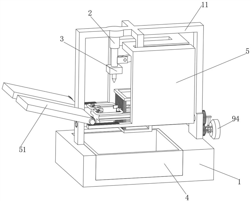
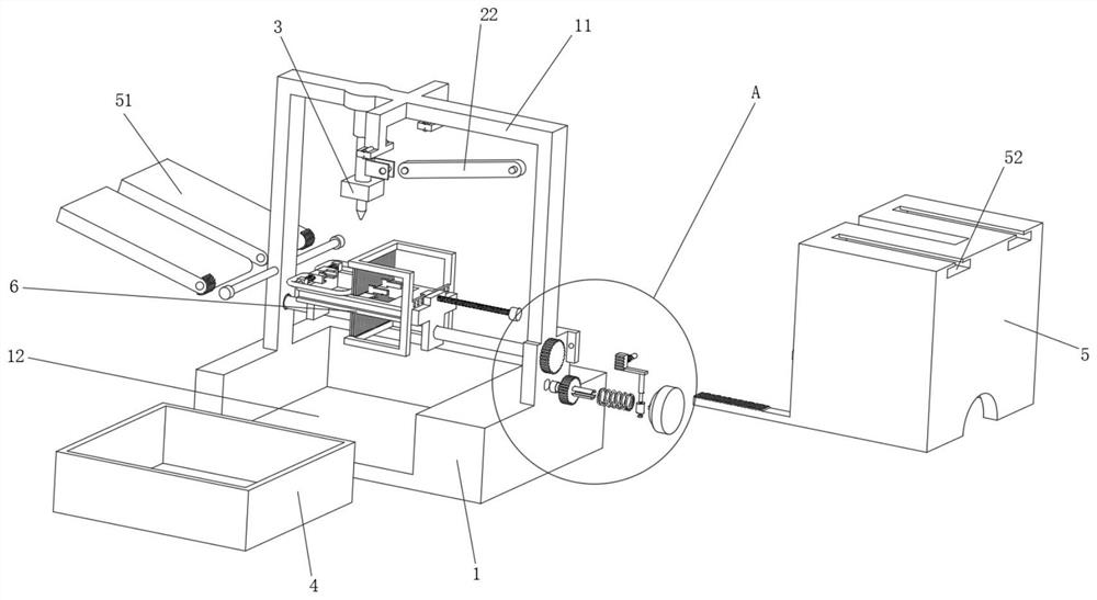
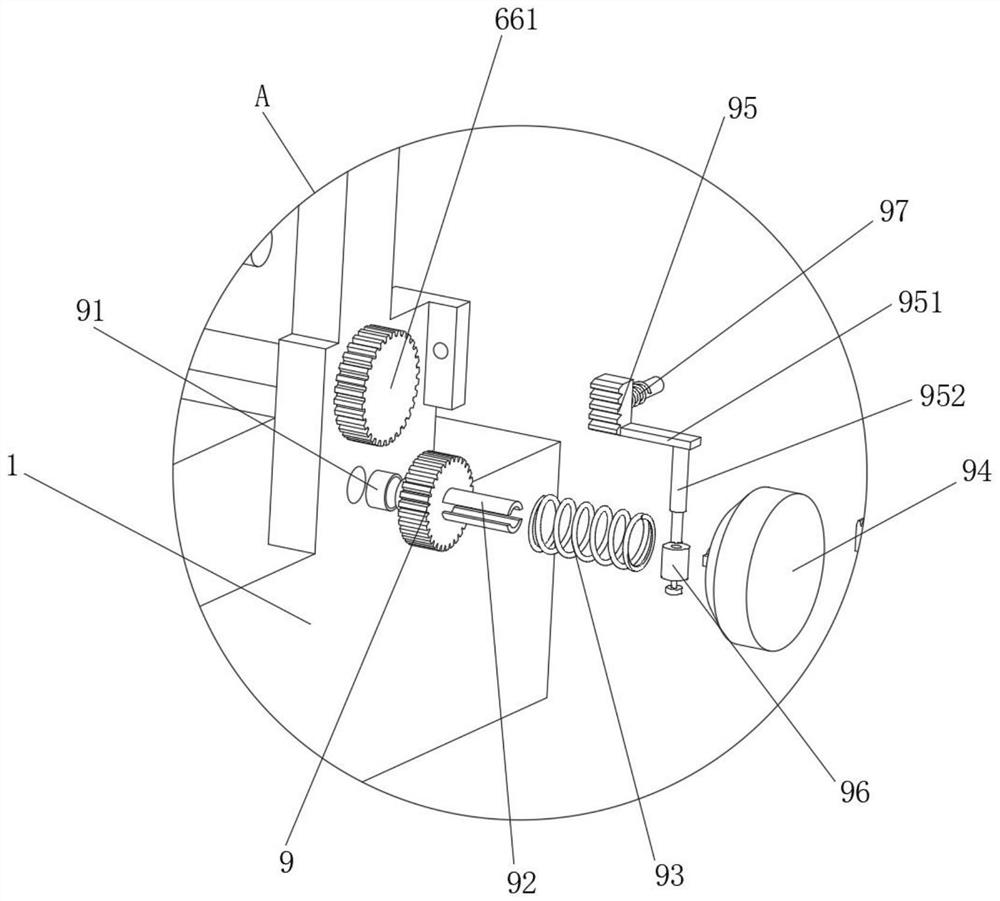
[0032] see Figure 1 to Figure 11 , the present invention provides a technical solution:
[0033] An intelligent soldering equipment for the production of integrated circuit boards of liquid crystal displays, including a soldering workbench 1, a mounting frame 11 is welded on the upper side of the soldering workbench 1, and a first bearing hole is opened on the lower side of one end of the mounting frame 11 111, the upper side of the first bearin...
PUM
 Abstract
Description
Claims
Application Information